I’m a residential contractor in Harwich, Mass., a coastal area with salty air, strong winds, and cold winters. For the past five years, my company has been building custom homes using the ReddiForm ICF (insulating concrete form) system. While I routinely use ICF foundations, many of my waterfront clientele have also elected to build with ICFs above grade. A recent project included an ICF home and a 24×36-foot freestanding two-story garage with a drive-in basement. The garage had a large single bay entry at the basement level, three car bays on the main level, and a home office upstairs. The garage itself was conventionally framed, but the main level had to be capable of supporting three vehicles, a considerable live load. While precast, hollow-concrete deck planks are available for this kind of application, I decided to check out an ICF-related system for pouring a structural concrete floor. The system, called Insul-Deck (Florence, Ky.; 800/475-6720, www.insuldeck.com), has been in use since 1978 and is licensed to ReddiForm under the name Reddi-Deck (ReddiForm, Butler, N.J.; 800/334-4303, www.reddiform.com).
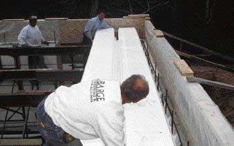
Pouring a heavy concrete slab over fluffy-looking EPS (expanded polystyrene) form panels may seem like taking the ICF concept a step too far. Actually, the Reddi-Deck system offers some advantages over precast concrete panels and conventional cast-in-place floor methods. The panels are lightweight — about 2 pounds per linear foot — and very easy to handle. Two workers can carry and place a 40-foot-long panel without a crane or much strain. The 2-foot-wide panels connect with a tongue-and-groove flange and assemble quickly.
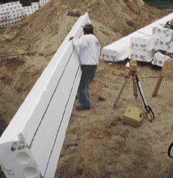
At roughly 2 pounds per linear foot, the interlocking deck panels can be carried and set in place by a single worker with relative ease.
Spans up to 40 feet are possible without intermediate support. The finished system is said to be less than half the weight of a comparable precast system. And the manufacturer claims that a trained crew can set the panels and steel reinforcement, ready for pouring, at a rate of 1 square foot per minute. That claim turned out to be fairly accurate in our case, even the first time out.
Stay-in-Place Forms
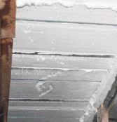
In essence, Reddi-Deck is a concrete-slab-and-joist forming system. The joist sections remain concealed within the EPS formwork, while the underside presents a completely flat, fully insulated ceiling profile.
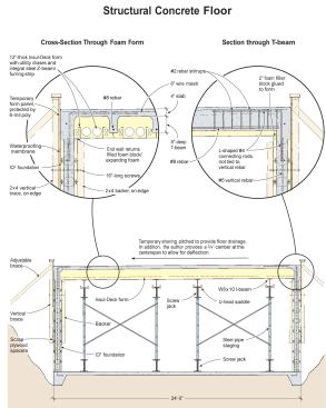
Conjoined foam panels create a negative form of the cast concrete "T-beam" floor system. The tongue-in-groove joist-forming flanges provide a positive seal against concrete leakage between forms. Integral utility chases provide convenient channels for plumbing, wiring, or hvac runs.
Inside each 2-foot-wide foam panel are two side-by-side 4 3/4-inch-diameter round “utility chases” and four 1 1/2-inch-diameter wire chases. A pair of integral lightweight steel Z-beams stiffen the form and allow clear spans up to 8 feet, including the live and dead loads of workers and concrete. The bottom beams of these are exposed on the underside of the form and provide visible, 12-inch-on-center furring strips for drywall or other finished ceiling.
The 12-inch-thick forms, capped by a 4-inch-thick slab, create a somewhat deeper floor system than a typical precast slab or a concrete-on-steel deck. But it’s no thicker than many I-joist floor systems, so, as long as any headroom issues and height restrictions are taken into consideration during the design stage, floor thickness isn’t a problem.
Two Pours in One
The Reddi-Deck system is designed to be compatible with an ICF wall system. As with a supporting masonry wall, the high compressive strength of the poured concrete wall provides more than sufficient bearing for the heavy (70-psf dead load) floor. And, by cutting the deck panels short enough to bear only on the inner edges of the ICF wall blocks, the wall cores remain exposed and accessible, allowing walls and deck to be poured together in a single continuous operation. This saves the expense of hiring a concrete pump twice.
Supporting walls. To set the wall forms, we first poured a 24×36-foot thickened-edge monolithic slab, level around the perimeter and sloped in the field to drain toward the drive-in end. We stacked the ICFs 9 feet high, adding horizontal #4 rebar to every other course of the foam blocks. In addition, we set vertical #5 rods in the center of every other cell, about 20 inches apart. The rebar is spaced and centered using proprietary wire chairs and guides. However, it’s important to have the rebar schedule designed or approved by a qualified engineer; the manufacturer suggests rebar weights, diameters, and distribution only for estimating purposes.
To brace the ICF forms, we use site-made 2×4 staging brackets, that both brace the forms and provide working access to the top of the wall. Adjusting screws at the anchor end of the diagonal braces make it easy to plumb the forms.
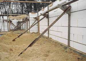
The author's site-made staging brackets provide lateral support to the ICF wall forms during the pour, as well as access to the top of the forms for pumping concrete and setting the anchor bolts and sill plate. Backers on the opposite side of the wall provide external bracing and catch the 16-inch-long screws used to attach the staging to the form work.
Backers. Since you can’t attach nails or screws directly to the foam, we use 2×4 backers on the opposite side of the wall forms. The backers also help to brace the wall form. We use 16-inch-long hex-head LogHog screws (Olympic Manufacturing Group, Agawam, Mass.; 800/633-3800, www.omgroofing.com), which I buy by the case, to attach the brackets. We drive them through the narrow edge of the 2×4 bracket uprights, through the foam, and into the narrow edge of the backers. By aligning the brackets over the webs in the foam blocks, rather than through the cells, we’re able to retrieve the screws for reuse. The best way we’ve found to drive the screws is with an electric impact wrench.
With the walls braced, we apply Sealtight, a self-adhesive waterproofing membrane (W.R. Meadows, Hampshire, Ill.; 800/342-5976, www.wrmeadows.com), to the exterior face (see Waterproofing ICF Foundations, 2/00). Ordinarily, I wait to do this until after the forms were poured and the bracing removed, but on the job shown here, I was concerned that the sandy excavation would begin to cave in and partially bury the walls while we waited for the deck forms to be delivered. It was a bit of a nuisance to remove and replace the backers to apply the membrane, and we had some little screw holes in the membrane to repair later, but this seemed like a smart trade-off against heavy shoveling and cleaning.
Perimeter Forms
To form the slab perimeter, we used full 4×8-foot sheets of 3/4-inch-thick Advantech subflooring, which we had on hand for the top floor. To protect it for reuse, we stapled 6-mil poly over it. We attached three 8-foot 2×4 vertical uprights on 4-foot centers to each panel, with a 2×6 “top plate” across the top. We attached these temporary forms end to end around the top of the wall, setting them 18 inches higher than the top of the ICF forms.
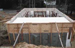
Perimeter forms were required to contain the edge of the poured floor system. Subfloor panels served temporary duty as form panels, attached in the same manner as the wall brackets, using 16-inch LogHog screws and 2×4 backers. Plywood scraps pack out the bottom of the vertical braces to hold the panels flush and parallel to the outside wall surface.
To attach the forms, we drove LogHog screws through the vertical braces and into 2×4 backers on the inside. Though we connected the top plate sections with short 2×6 scabs, we still had some bulging at the top edge during the pour, which we fixed with screw jacks. But in the future, I’ll use a continuous second 2×6 plate to reinforce the top edge.
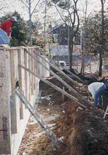
Excavation made it difficult to install counter bracing on the exterior side of the wall. However, it proved to be essential to countering the tendency of the perimeter forms to bulge outward during the pour. Screw-jack adjustments at the base of the braces pushed the forms back into position.
Falsework
Like any cast concrete, cast-in-place joists attain the designed structural properties only after a minimum 28-day curing period. During the pour and the entire curing period, the floor system is supported by “falsework,” or temporary shoring under the forming panels. At 70 psf, the weight of this 864-square-foot floor would top 30 tons.
I opted to rent ready-to-go falsework from A.H. Harris (860/665-9494, www.ahharris.com), a large concrete contractor and forming consultant that serves New England, New York, New Jersey, and Virginia. The company provided a layout plan for the falsework, ensuring that we’d have the proper spacing and support for the overhead concrete. The entire package cost about $1,000 for a one-month rental.
The falsework consisted of heavy-duty 4×6-foot steel pipe staging, with screw jacks top and bottom. Each leg was rated for a working load of 12,000 pounds. On top of the staging, W8x10 I-beam strongbacks, set in U-head saddles over the upper screw jacks, provided distributed support for the deck forms.
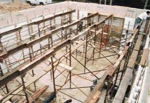
The deck pan was supported by a series of 4×6-foot steel frames and braces, topped by sectional steel I-beam strongbacks. The strongbacks were arranged in four parallel rows on nominal 7-foot centers.
The falsework was delivered by flatbed trailer; but the truck couldn’t make the turn through the subdivision’s narrow stone gate. We ferried the frames and accessories to the site on a smaller trailer, making a couple of trips. None of the equipment was particularly heavy; at 13 pounds per linear foot, the I-beams were the heaviest pieces, but none was over 7 feet long. This was an unanticipated snag, however, and had we ordered precast deck planks or panels, the problem would have been much harder to solve.
We set the frames, braces, and beams up in four parallel rows running the 36-foot axis, according to the shoring plan.
Drainage slope. We pitched the falsework to provide floor drainage toward the overhead door side by raising the opposite side 2 inches over the 24-foot-wide span. Not only is such drainage for a garage floor required by code, but given the building’s proximity to the ocean and salt spray, I wanted to make sure that salty water couldn’t puddle and soak into the floor and corrode the reinforcement steel. To ensure a flat surface, we stretched a stringline across the 24-foot end wall to represent the finished floor line at the planned pitch, then laser-leveled each strongback course at its location along the line. Because the ICF blocks were level around the perimeter, we glued 2-inch-wide foam rippings along the top of the 36-foot side. Expanding urethane foam is the ICF adhesive of choice. We used a combination of foam rippings and expanding foam to fill the tapering, 24-foot end-wall returns.
Camber. To compensate for the calculated dead-load deflection, I also planned to introduce a 3/4-inch positive camber at center span. I didn’t want the floor to settle and allow water to puddle. We raised the two middle strongbacks higher than the two outside courses, creating a convex floor profile across the foundation. The screw-levelers enabled us to make precise adjustments to the floor line.
The 24-foot-long panels were shortened to bear only on the inner edge of the foundation forms. A recip saw was used to cut through the integral steel Z-beams.
The entire 24×36-foot deck was covered within an hour.
Placing the Panels
The panels were delivered in full, 24-foot lengths. But to fit inside the wall forms and leave the ICF cells exposed for filling, they had to be shortened. If not for the integral steel beams, this could be done with a hot wire. But it wasn’t much more difficult to cut them with a recip saw fitted with an aggressive hacksaw blade. Once all the forms were trimmed, we stood on the strongbacks and staging planks to set the first panels in place, then moved onto the last panel placed to complete the installation. We had all the panels placed within an hour.
The tongue-in-groove flanges snugged up to one another easily, although some of the panels had some overall sideways curvature, probably caused during shipping. We placed all the panels, then forced the curves out by wedging and blocking at opposite ends of the deck. To prevent the panels from springing and separating, we screwed 1x cleats to the underside, using the integral Z-beam flanges for attachment.
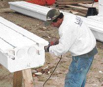
Our site supervisor, Al Wood, beveled the panel ends to ease the concrete over the deck-to-wall transition.
Form edges are eased to reduce the likelihood of a stress crack forming at the transition from horizontal to vertical concrete. The site supervisor approximated the panels' factory longitudinal bevel across the end cuts, using a reciprocating saw.
The foam panel flanges are fragile and withstood some slight damage in shipping and handling. We used expanding foam to rebond a few breaks and fill small gaps and seams.
It’s important to close the chases at the panel ends so the concrete doesn’t go wandering off where it doesn’t belong. Reddi-Deck offers proprietary foam plugs to cap the ends of the 4 3/4-inch-diameter utility chases. The smaller, 1 1/2-inch chases are easily closed with a squirt of expanding foam.
Steel Reinforcement
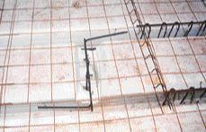
Horizontal, free-spanning concrete calls for careful scrutiny to make sure it’ll perform properly under varying design parameters. Rebar gives tensile strength to the cast joists; without it, the floor would simply collapse under its own weight. The rebar must be installed on the tension side of a beam to be effective — in this case, near the underside of the joists. We placed it on plastic chairs set on the bottom of the form channels. The chairs are designed to suspend the rebar at the proper depth to ensure full embedment in the concrete. The manufacturer’s estimating schedule specified two pieces of #5 (5/8-inch-diameter) rebar per joist for the proposed 24-foot span. I thought that would be too cumbersome to place and tie within the relatively narrow joist forms. Instead, I wanted to use a single length of #8 (1-inch-diameter) rebar in each joist. My engineer calculated the loading on a single joist, assuming a vehicle weight of 1,000 pounds per wheel and an 11-foot wheel base for his load analysis. The #8 bar was more than adequate.
Stress relief. I had planned to tie the horizontal rebar in the joist channels to the vertical rod in the wall forms. However, my engineer was concerned that that would create a moment connection that could transfer undesirable stresses to the lower section of the wall. In the event of floor movement, expansion, or contraction, he wanted any likely cracking to occur right at the floor-to-wall junction, instead, so we cut the vertical rods flush with the top of the wall forms and used independent, L-shaped horizontal #4 connecting rods to tie the floor to the walls. These connecting rods extended 3 feet onto the deck and rested on 3-inch-high wire chairs, with a 2-foot leg hanging down into the wall cells.
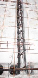
The right-angle connecting rods were tied to the #8 longitudinal rod with #2 rebar stirrups, placed 5 inches on-center over a 3-foot run.
To eliminate a moment connection, steel rebar connecting the floor system to the walls was installed independent of the wall rebar, providing for possible movement in the floor to be released at the top of the wall.
We united the connecting rods and the horizontal #8 rod with a series of #2 rebar stirrups, placed 5 inches on-center and tied to the connecting rod with wire twists. We also ran horizontal rods around the entire deck perimeter for a bond beam effect.
To reinforce the concrete slab, we capped the panels with 6-inch wire mesh, placed above the forms on wire chairs.
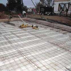
Welded 6-inch-square steel fabric was placed over wire chairs and wire-tied to the perimeter rebar to unify the floor system.
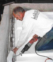
To allow use of a chain fall or hoist in the lower garage bay, I also installed a rugged attachment point in the ceiling near the overhead door. I used standard, L-shaped foundation anchor bolts, punched through the bottom of the form inside a scooped-out access hole. I tied each bolt to a length of rebar that engaged an adjacent joist form. The access hole penetrated a utility chase, which I capped with expanding foam to keep out the concrete.
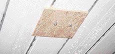
The bolts will be used to attach a rugged bracket to the ceiling below.
The bolts are set in a cavity scooped out of the deck form and tied to rebar extending back to two adjacent joists.
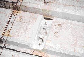
To provide for a chain fall or hoist, the author installed a pair of foundation anchor bolts through one of the floor forms.
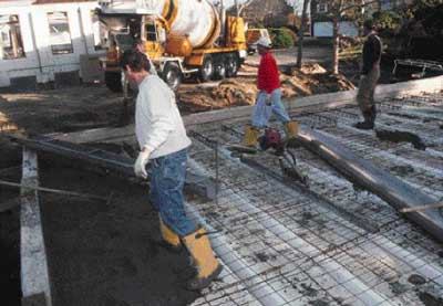
The Pour
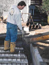
My flatwork sub, Will Daniels, placed a 5,000-psi mix in a continuous pour to the prescribed 4-inch floor thickness over the forms. Will noted that the foam panels felt sturdier underfoot than any all-steel pan system he’d worked on. We were able to pull the mix truck up near the top of the wall and chute the mix around the floor. This was really convenient, because, ordinarily, the cellular configuration of the wall forms requires the mix to be pumped. The deck pan and the running gap around its edge enabled us to distribute the concrete to the perimeter without the added cost and hassle of pumping.
Bad vibes. We used a cordless concrete vibrator to move and settle the mix. I like the cordless tool because it’s less aggressive than a typical corded vibrator, providing just enough temporary flow and plasticity to settle the mix without overpressurizing the ICFs. Nonetheless, it pays to be cautious. Al Wood kept an eye on the underside of the system as we poured. A good thing, too, because he noticed the 2-inch foam spacers we’d installed to help slope the deck pan begin to bulge and move off the blocks at the middle of the 36-foot-long wall. I backed off vibrating in that area, and we avoided a blowout. In hindsight, we could have screwed a retaining cleat to the underside of the deck forms, attaching it to the integral steel furring flanges, to prevent the spacers from moving.
Backing off on the vibration averted a blowout.
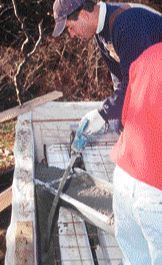
The pressure generated by vibrating and compacting the concrete began to force pieces of retrofitted foam blocking out of place, despite the use of foam adhesive.
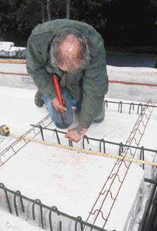
We installed a wood screed strip, set by laser line, along the inside face of the perimeter forms to control the finish floor line. The strips were diagonally ripped from 1×4 mahogany decking and installed square edge up, leaving a beveled slab edge when removed.
A triangular wood screed strip attached to the wall form guides the thickness and slope of the floor and provides a beveled edge to the finished slab.
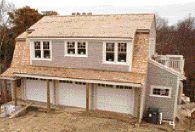
A views of the project after completion.
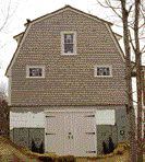
A views of the project after completion.
Strength in unity. The resulting floor system is a seamless, organic whole; the joists support the floor slab, while the slab contributes its thickness to the joist depth and distributes dead and live loads across the joists. The system provides the maximum strength of a reinforced concrete deck using a minimum of material. Although the induced camber was intended to offset the anticipated 3/4-inch dead-load deflection, the floor retains a slightly crowned profile. Should deflection occur under live loading or due to settling over time, the resulting stress may cause cracking at the deck and wall junction. However, that would in no way compromise the strength or integrity of either system.
The final cost of the slab was $16.60 per square foot, including steel, concrete, the forms, the falsework, and labor. Todd LaBarge is a residential contractor and structural engineer in Harwich, Mass.