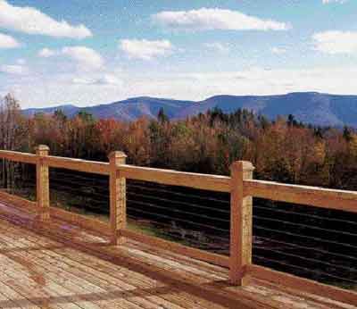
Stainless steel cable railing is low maintenance and long-lasting. It’s also fairly easy to install: Horizontal cables are strung through holes drilled in railing posts and tightened with cable studs — fittings that grip the end of a cable run and allow it to be tensioned —until they “sing.” With its open, airy design, cable railing virtually disappears, providing an unobstructed view and a clean, contemporary look.
My company specializes in building decks. Though cable railings don’t make up a large percentage of our work, we have seen an increase in demand for them since they were approved in recent versions of the building codes. Many customers ask about cable railings but lose interest after learning that they cost almost twice as much per foot as wood ones.
I buy cable in bulk and have the fittings I need made in a local millwork shop. This substantially reduces my material costs compared with using an off-the-shelf cable-rail system. For convenience, however, you may want to consider one of the available packages if you’re doing only one deck (see “Buying Components”).
Cable and Posts
Cable comes in diameters of 1/8 inch to 1/2 inch, in 1/16-inch increments. The sizes most often used for residential applications are 1/8 inch, 3/16 inch, and 1/4 inch. With very large posts — say, 10-inch-diameter logs — the larger 1/4-inch to 1/2-inch cable should be used, to balance the look of the railing. For commercial applications, 3/16 inch is the smallest size allowed, but 1/4 inch is recommended. In my area, 3/16-inch cable runs around 80 cents per foot when bought in 100-foot rolls.
Stainless Steel Cable ConfigurationDifferent configurations of stainless steel cable vary in flexibility. For example, semiflexible 7×7 cable has seven cords, each with seven individual wires; it’s used for straight runs and corners where cable runs between multiple posts. The smooth cable preferred by most customers is 1×19 rope, made by twisting 18 wires around one center wire. Since it’s semirigid, it’s used for straight runs and gentle turns. 1×19 cable 7×7 cableStainless steel is an alloy of iron and carbon that contains between 12 percent and 30 percent chromium. The chromium forms an oxide film on the surface, which is what gives stainless its superior corrosion resistance. Still, the alloy can discolor or rust if it comes in contact with chloride salts or sulfides. There are several grades of stainless steel. Type 303 contains sulphur to enhance machinability; typical applications include bolts, bushings, nuts, and shafts. The most widely used stainless for aesthetic purposes is type 304, a low-carbon, general-purpose alloy. Type 316 is the most corrosion-resistant form commonly available; it contains extra nickel and molybdenum and is used in marine environments. It’s also the type most often used for cable railings. |
Posts can be made of a variety of materials, such as wood, powder-coated steel, and powder-coated aluminum. Cables should be spaced no more than 31/2 inches apart, so that a 4-inch sphere can’t pass between them (code requirement). This means there are at least nine cables on a 36-inch-high residential railing, and since each cable exerts roughly 300 pounds of tension, the posts need to withstand a minimum of 2,700 pounds of pull. Posts require stout mounting plus a cap rail that spreads the load out from the anchor posts to the intermediate posts.
Most wood 4×4 posts can withstand these pressures. Because cedar is so soft, though, you must use wider washers at cable terminations to prevent the cable from pulling through — and you should consider using larger posts, such as 4x6s or 6x6s.
Steel posts can be 1-inch-by-3-inch flat bar, 2-inch-by-2-inch-by-3/8-inch angle, schedule-80 pipe, or 1/4-inch walled tubing. With all steel posts, you need to use sleeves of rubber, nylon, or stainless steel to separate the cable from the steel and prevent wear. Aluminum posts of the same dimensions can be used, but 2-inch-by-2-inch angle must be beefed up to 1/2-inch thickness.
Do not attempt cable railing with solid composite posts, as they will warp when the cables are tightened. Composite or plastic sleeves that fit over a wood post are fine.
Post Configuration
You can use single-posted or double-posted corners. Post spacing should be determined according to the strength of the top rail, which — according to code — needs to withstand 200 pounds of pressure in any direction (plus help spread out the tension from the cables to the other posts). Most railing materials are limited to 6 feet or less, though with engineering, steel railings can exceed 6 feet.
Single Post
Single Post Double End
Double Corner End Posts
Double Corner Posts With Pass-Through
In most cases, the rail can span a greater distance than the cables. The smaller the cable, the closer together the posts need to be — no more than 36 inches between posts for 1/8-inch cable, 42 inches for 3/16-inch cable, and 48 inches for 1/4-inch-diameter and larger cables. If you want a more open look, you can avoid placing full-sized posts midspan by substituting “stays” — thinner pieces of steel, aluminum, fiberglass, or wood. The cables run through holes drilled in the stays.
Because long runs are harder to tension, I try to avoid straight runs of cable longer than 80 feet. For runs that have one or two 90-degree corners or up to four 45-degree corners, 40 feet or less is the rule of thumb. End posts need to be spaced away from the building to allow for tightening the cable. When the face of an end post is exposed, the ends of the studs are covered with caps that can be removed for subsequent tightening.
When using wood posts and rails, I order all the railing components before building the deck. If I’m using a welded steel or aluminum frame whose dimensions can’t be easily changed, I order it after the deck is built. I like having the flexibility to make changes in the deck framing without worrying about the railing being exactly right.
Cable Connections
The machine shop I use makes the cable studs from 4-inch lengths of 1/4-inch 303 stainless rod. The shop drills a 1/8-inch hole down the center of one end to a depth of 1 1/4 inches, and threads the other end for 2 1/2 inches to take a 1/4×20 nut. The stud slides over the cable and is swaged, or crimped, with an H.K. Porter swaging tool ($110; 919/362-1709, www.cooperhandtools.com). Swaging makes a strong, permanent connection.
Alternatively, the Atlantis Rail System uses a mechanical swaging that is an integral part of its universal turnbuckle. Its ball joint and flange mount allows it to be used for straight runs, turns, or stairs. Tightening a cap nut secures the cable — no swaging tool needed, just a wrench. The turnbuckle screws to the inside of the post, so it can be installed tight to the building. The screw attachment also saves time that would otherwise be spent drilling the end posts. Though it costs about $14, this is the only commercial stud I would use.
For short runs — straight runs up to 40 feet or runs of less than 20 feet that have one corner — studs aren’t needed at both ends. Instead, one end (usually on the far side of the last post) is anchored with a swaged cable stop and washer. Cable stops, which are available from any professional fastener supply shop, are simple 1/2-inch-by-1/2-inch aluminum tubes with a hole sized to fit the cable. For the stops, I drill a 3/4-inch-diameter hole 3/4 inch deep, then continue through with a small hole sized for the cable. If the posts are ACQ-treated lumber, I make sure to use stainless steel stops.
Preparing Posts for Cable
The first step in installing a cable railing is locating the posts and making sure they’re spaced to support both the upper railing and the cable. The post locations dictate how to drill the posts. For example, single-post corners get holes that curve, while double-posted corners are drilled straight through. Posts at stairs need angled holes.
I drill straight through most posts, using a bit that’s 1/16 inch larger than the cable size. To drill accurately, I use a simple jig made from a piece of 1×4 the height of the posts, with guide holes where the cables are located. I use a Milwaukee Pathfinder bit to drill the curved holes in single-post corners; I start these holes from each side and join them in the middle. Milwaukee no longer makes Pathfinder bits, but Bad Dog Tools (800/252-1330, www.baddog tools.com) has similar ones (Figure 10). Single posts on 45-degree corners are mounted at 22.5 degrees and drilled straight through.
End posts need two-step holes to fit the cable stud, washer, and nut. I use a 5/8-inch Forstner bit to drill a hole about 2 inches deep for the washer and nut. I center a 1/4-inch bit in the 5/8-inch hole and drill the rest of the way through for the cable stud. (The Forstner bit makes an indentation in the center so you can line up the 1/4-inch bit.) It’s important for the larger and smaller holes to line up, because there’s little room for a 9/16-inch washer and the cable stud to align.
To find the right angle for drilling the stair posts, I use a 6-foot level, a Speed Square, and a torpedo level. After cutting a small angle block for guiding the drill, I make a hole halfway through the post with a 6-inch-long drill bit; then I remove the guide and continue to drill through.
If the stair post is going to be used as an end post, it will also need a two-step hole to accommodate a cable stud or stop. This can be tricky to drill. I use the angle block and a Forstner bit with a drill stop mounted 2 inches back from the cutting head. I start drilling with the bit vertical, then carefully tip it back to meet the guide block and continue to drill until the hole is 1 1/2 inches deep.
Capping and Cabling
Once all the posts have been installed, the top rail is fitted between them to resist the tension when the cables are tightened. The decorative cap is then installed continuously over the top rail and the posts.
Cable comes on a large spool, which I mount on a spindle so that it feeds easily from post to post. It’s usually best to set up the spool so that it feeds straight into the end post — generally an end post that’s not against the house. Before threading the cable, I wrap the end with tape to keep it from fraying on its journey through the holes. A $24 HIT Tools 22WRC75 cable cutter (909/974-0369, www.hittools.com) cuts the cable cleanly. Once the cable is fed through all the posts, I swage a cable stud or a stop to its end.
The next step is pretensioning, or stretching the cable tight before putting on the end stud. If you skip this step and rely only on the threaded studs for tightening, you may run out of thread before the cable is tight enough. Then you’ll have to cut off that stud — now expensive scrap — and swage on another.
Pretensioning is done with locking pliers, scraps of wood or composite decking slit to fit over the cable, and wedges. Working back from the first end post, I pull the cable hand-taut and slip a piece of wood over it on the pull side of the post. With the locking pliers, I gently grip the cable right behind the block. Then I drive the wedges between the block and the post to tighten the cable. Next, leaving the pliers and wedges in place, I jump ahead three or four posts and repeat the process. I pretension at every corner and typically use four or five pairs of locking pliers in a run.
With the cable taut at the last post, I cut it to fit in the stud so that there’s just enough thread left to engage the nut. I swage the cable stud, slip it into the end post, and tighten the washer and nut. I install the rest of the cables the same way.
Once all the cables have been pretensioned, it’s time to fully tension each one. There is a correct sequence to this: Start with the center cable, then tighten the remaining cables by alternating above and below the center cable. All cables should be of uniform tension, with no sag. Each should sound the same note when plucked.
The final step is to cover the holes in the end posts. I rip a 1/4-inch-thick by 11/2-inch strip of the same material as the post, cutting it long enough to hide all the holes. This I attach with three stainless steel screws, for easy removal in case the cables need tightening.