
On a recent project that was typical of a lot of the structural repairs we do along the southern coast of New Jersey, we encountered serious rot in many of the dimensional and engineered wood beams. The beams were not detailed well for protection from the driving coastal rains we encounter in this region. It’s a tough environment for wood: Not only do we get lots of wind-driven rain, but the ocean air is high in humidity year round. When wood doesn’t have a chance to dry, it will rot quickly—and engineered materials with all their adhesives are no exception. Waterproofing for these conditions is not just about deflecting water away from the building; you also need to create a way to drain the building assemblies and allow air to flow over the wetted structure to promote drying.

The Problem
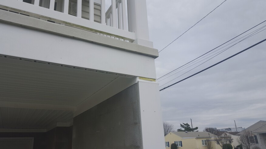
The problem was originally discovered by one of the condo-unit owners, who saw water pouring out of the aluminum capping that covered a beam above his second-floor balcony. We were contacted to investigate the leak and discovered mold and rot in the beam under the capping. The balcony on which we were standing was supported by a similar beam, in the first-floor ceiling of the carport. We also removed the cladding from this beam, and discovered similar conditions.


Because the complex was less than 10 years old, the homeowner warranty would cover the repairs, so the insurance company was contacted. Since the beams are considered common elements and are not the responsibility of the individual owners, but of the condo association, all the beams in all three buildings of the complex had to be stripped of cladding and examined. Once the cladding on the remaining beams was removed, it was discovered that many of them were in very poor condition.
A consulting engineer was hired to examine the beams and surrounding structure to determine which beams needed to be replaced and which were still structurally sound. In the final tally, nine engineered beams and two dimensional-lumber beams had to be replaced. Based on the engineer’s findings, one of the unit’s beams was so deteriorated that the structure was deemed unsafe to inhabit and would need to be temporarily shored for the rental season. The engineer provided a temporary shoring plan, and we were able to support both the balcony and the third-floor bedroom without limiting access or use of the areas.
The Cause
The beams were clad with aluminum trim coil that was trapping water at the bottom of the assembly. Bad as that detail was, it might have been all right if the top of the beams had been protected, but that was definitely not the case.
The second floors of the buildings have a decorative band around the perimeter that forms a break in the siding and consists of a 2x8 capped in aluminum trim coil. Where this band passed in front of the beams, it was applied over the sheathing and housewrap. This allowed water into the trough created by the capping under the beam.

Some of the lower beams had OSB sheathing on the front of them, which made them protrude past the front edge of the fiberglass balcony. This allowed the water running off the balcony to flow directly into the capping. All the buildings lacked gutters, as well, so when it rained, roof runoff flowed straight down the vinyl siding.

Once we had the list compiled of the beams that needed to be replaced, we hired an architect to specify new beams and create a replacement plan. The existing structure had been built with a combination of both treated and untreated glulams and Parallams, which would be replaced with exterior-rated Parallam beams.
Jobsite SetUp
We worked on two units at a time with a four-man crew. We accessed the second-floor balconies from 12-foot planks on pump jacks, and for the lower beams, we primarily worked off rolling staging.
On previous projects of this type, we constructed temporary 2x4 walls under every beam we replaced, to support the floor load above. This was time-consuming and produced a lot of waste. The temporary walls were also very intrusive, limiting access and work space.

To avoid this frustration, we recently started building modular supports, which have worked great. These consist of a bottom beam to distribute the load across the floor; adjustable Lally columns; and an adjustable support beam across the top.
The bottom beam is a 2x12 plate with a 2x4 on edge making an upside-down T. Over this, we put an upside-down U made with two 2x4 sides and a 3/4-inch-plywood top. Essentially, we have three 2x4s for bearing on a 2x12 plate, but the assembly is sectional, so it’s not too heavy to move from job to job.

The top support beam is made with light-gauge steel that fits into an upside-down-U pocket consisting of a 2x12 plate and two 2x6s on edge. We drilled slots in the 2x6s and a hole in the steel beam for a pin. The top plate is screwed to the ceiling framing, and then the beam is slid in and hangs until the posts are installed. For this project, the posts were set at just under a 12-foot span. We have a third pole for the center if needed to support loads across longer spans.
To prevent damage to the fiberglass decks on this job, we laid down slip-resistant canvas drop cloths and 5/8-inch plywood for a working surface, which we installed before setting our temporary supports.
The Solution
After removing the aluminum capping, siding, and soffits, we discovered that much of the surrounding sheathing and some of the framing was also compromised. We had included most of this in our scope of work, as we had assumed that if the beams were wet, the areas around them would be also.

Removing the beams required cutting through a lot of nails, many of which were hidden or difficult to access. In the upper beams, there were toenails that secured the trusses above and the 6x6 posts and king and jack studs below. A couple of the beams also held drywall screws, which led to drywall repairs and repainting on interior walls.
On the lower beams, we removed and disposed of the hangers, as well as toenails, that secured the balcony joists. (We would later replace them with stainless steel hangers and fasteners because we were close to the ocean.) The plywood for the fiberglass balcony was nailed into the top of the beam, and finish nails secured a 1-by fascia board to the exterior face of the beam. The beams sat on bearing walls at each end and were nailed off to these wall plates.
In addition to all those fasteners, we had to cut or remove multiple straps between the beam and surrounding framing, along with lag bolts that attached the balcony railing posts. To cut the fasteners, we relied on a combination of reciprocating saws, oscillating tools, and grinders.
After all of the fasteners were out of the way, we were able to cut the old beams out. Some of them came out in two pieces and were easy to remove, while others had to be cut into multiple pieces and required much more time and effort.

Once we had a clean space, fitting the new beams required some finesse. The old beams had compressed at their bearing points, and the new beams did not always have the necessary clearance. But this is where the adjustable columns used for our temporary supports came into play and made the job simple: We were able to slightly lift the structure with the screw jacks to gain the space we needed.

Once the new beams were in place, we partially loaded them before nailing them off and removing the temporary supports.
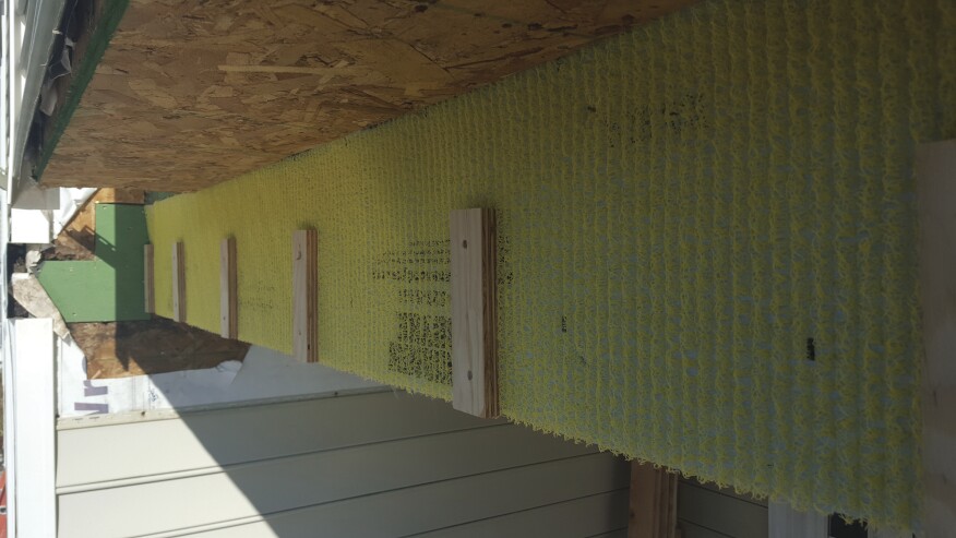
To protect all the new beams from water and prevent a repeat of the rot, we installed Home Slicker, a matrix-type rainscreen, to the exterior side of the beam. We then installed 2-inch-wide strips of 3/4-inch marine plywood before attaching a 2x8 band. This assembly allows for unrestricted water flow for rainwater or snow melt that makes its way past the siding and flashings, and it provides plenty of room for air flow for drying.
On the inside of the beam, we installed Tyvek housewrap to isolate the aluminum trim coil from the pressure-treated beams. On the bottom of the beam, we installed vented soffit to allow water out and air in; and for both the exterior and interior sides of the upper beams, we used L-shaped bends of aluminum capping. On the exterior, we installed a Z-bend that was taped to the sheathing under the housewrap and bent over the top edge of the band board. This will force any water that makes its way behind the siding to the outside above the beam. On the lower beams, the capping was slid between the fiberglass fascia and the beam to limit water getting between the cladding and the beam.
All damaged sheathing was replaced with water-resistant Zip sheathing before the housewrap was repaired and the siding reinstalled. While removing the siding and soffits, we had labeled all the pieces, which made putting them back together much easier.


