

When Hurricane Michael slammed into the Florida Panhandle last year, it damaged or destroyed thousands of structures. But as always in a major hurricane, a few well-built homes stood out as examples of how rugged construction can stand up to a storm. In one example, six small Habitat for Humanity houses in Panama City came through Hurricane Michael essentially unscathed, even as the homes around them lost their roofs and suffered significant structural damage.
The six houses were part of the “Habitat Strong” program, an above-code construction program modeled on the recommendations of the “Fortified Home” program developed by the Institute for Business and Home Safety (IBHS), an insurance industry nonprofit that advocates for more-resilient building practices. Framed by local builder Eric Anderson (Compass Homes of Northwest Florida), the houses boasted beefed-up roof details and an engineered design featuring a continuous foundation-to-ridge load path. But according to IBHS, the added features that contributed to the buildings’ exemplary performance added only a modest amount to the affordable structures’ cost.

From one house to the next, components and details may vary, said IBHS Market Development Manager Alex Cary, herself a licensed builder in Alabama. But the concept of a continuous load path is consistent, she explained in a JLC interview. “It [the Fortified standard] just says that it has to be an engineered design,” said Cary, “because there’s a million ways to skin that cat.”
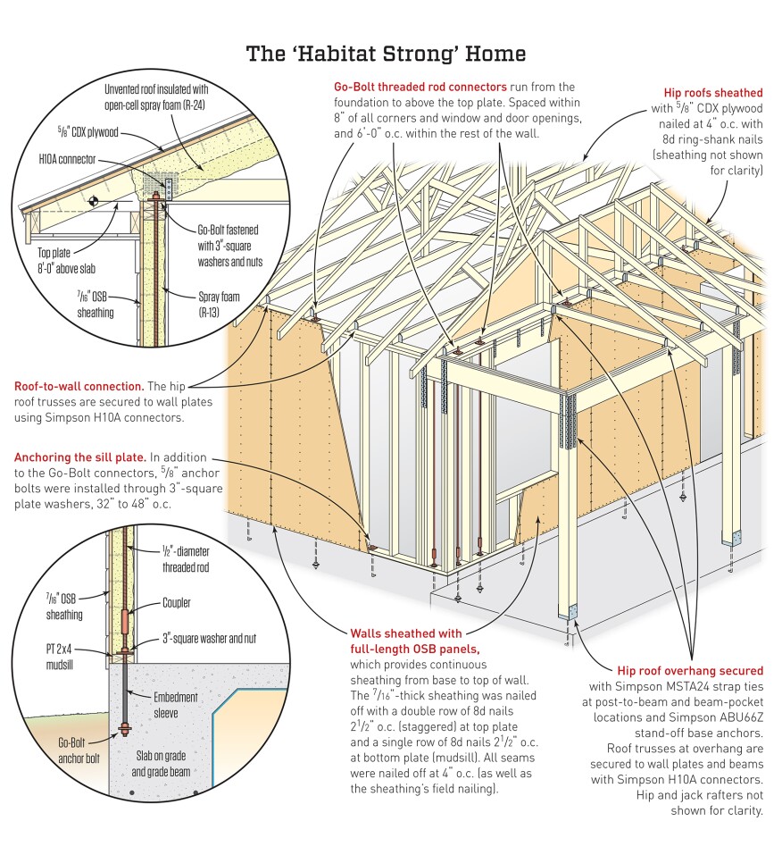
In this case, builder Eric Anderson applied the same construction details that he typically includes on his market-rate houses. (“I build above code,” said Anderson.) To resist uplift, Anderson installed the “Go-Bolt” system (go-boltinc.com), developed by a Florida builder after Hurricane Andrew. Go-Bolt adapts the reinforcing concept often used in concrete masonry block construction and applies it to stick framing. The method relies on threaded rod connectors that run all the way from the foundation to above the top plate, tied to anchors embedded in the concrete at the foundation, and fastened down over the top plate with 3-inch washers and nuts. “I’ve got them within 8 inches of the corners, within 8 inches of every opening, and then spaced every 6 feet within the rest of the wall,” said Anderson.
Anderson fully sheathes his stud walls using long-length Windstorm OSB panels from Norbord (norbord.com), which allows continuous sheathing from the base to the top of the wall with a single long sheet of OSB. At the top of the wall, he specs staggered nailing at 2 1/2 inches on-center into each of the double wall plates. The plate at the base of the wall also gets nails at 2 1/2 inches on-center. Sheathing is nailed to studs at 4 inches on-center, in the field as well as at the joints. On the Habitat projects, Anderson uses galvanized 8d nails, hand-driven by volunteers. On his regular jobs, his crew uses gun nails, but they follow the same tight nailing pattern.
Roof trusses are secured to the wall plates using Simpson Strong-Tie H10A connectors. The Habitat houses have hip roofs, sheathed with 5/8-inch CDX plywood nailed at 4 inches on-center with ring-shank nails. The entire roof is covered with peel-and-stick bituminous membrane and roofed with 24-gauge steel roofing. The roofs are unvented, said Anderson, and insulated with spray foam (as are the walls).

Understanding the Load Path
Anderson’s above-code details are a package deal: Omit any particular item, and the house could fail at that location. That’s the whole idea behind the load path: A house is only as strong as its weakest point. To learn more, JLC talked with engineer Mary Uher, a region manager with the Field Services Division at APA - The Engineered Wood Association. Said Uher: “We all know that a chain is only as strong as its weakest link. We have to think of a house as a chain. So we have to be able to tie the roof to the walls, the upper-floor walls to the lower-floor walls, and the walls to the foundation; and then the foundation has to be big enough to get the load into the ground.”
The requirement for a complete load path is written into the building code. The 2015 International Residential Code (IRC), Chapter 3, states: “The construction of buildings and structures in accordance with the provisions of this code shall result in a system that results in a complete load path that meets the requirements for the transfer of loads from their point of origin through the load-resisting elements to the foundation. Buildings and structures constructed as prescribed by this code are deemed to comply with the requirements of this section.”
If you want to exceed bare minimum code, it’s important to do so throughout the load path. Most framers intuitively understand gravity load paths. You’re working against gravity the whole time you’re framing, and you typically have a gut feeling about whether a structure you frame is going to stand up. But wind loads aren’t so easy to grasp by instinct, and it’s quite common for framers to leave one weak connection in an otherwise strong building.
The photos below show failures in the upper portions of houses.


APA Above-Code Recommendations
APA’s publication “Building for High Wind Resistance in Light-Frame Wood Construction” offers a detailed set of prescriptions that exceed the code minimum. In describing the recommendations, Uher thinks like an engineer: She starts at the top of the building with the roof sheathing attachment. “Code minimum is 6d common nails 6 inches on-center on the end of the panels, and 12 inches in the field,” said Uher. “If you use an 8d deformed shank fastener—that is, a ring-shank or screw-shank fastener—and tighten that nailing pattern to 4 inches at the ends and 6 inches in the field, it creates a much better performance, and your roof is more likely to stay attached to your trusses.”
Next in line is the roof-to-wall connection, where the rafters or trusses connect to the walls. Here, there are multiple options for an upgraded connection. The basic recommendation is for a steel connector between each truss or rafter and the top plate. The ideal connector should resist forces in three dimensions: up and down, side to side, and in and out. A good example of a connector that works this way is the SST H10A clip.
Another advantage of the H10A connector is that it reaches down far enough below the truss to tie into the bottom member of a double plate. In buildings damaged by high winds such as tornadoes, Uher noted, it’s typical to see top plates separated by the wind forces. “Everyone knows that nails are the worst in withdrawal,” said Uher. “The top plates are held together by a couple of nails, and they can separate. So we recommend a connector that ties both those top plates together.”
Rather than a steel plate connector, you can use structural screws up through the wall plate to connect a rafter or truss to the plate. The screws typically cost more than steel connectors, but may be faster to install, noted Uher.
In some situations, sheathing and nails can be used to create the appropriate connection. “If you have a raised heel truss, you can use your wood structural panels to transfer that load down into your wall,” said Uher. An APA publication, “APA System Report 103: Use of Wood Structural Panels for Energy-Heel Trusses,” provides guidance for engineers on how to specify that assembly for various wind load situations so that the wall sheathing can serve as part of the load path.
In any case, Uher said, it’s critical to make sure that the wall sheathing is attached to the wall top plate. In field investigations, teams have seen cases where the trusses stayed attached to the wall plate, but the wall plate simply separated from the wall. Four-inch-on-center nailing into the top plates makes this failure less likely.
Another problem area is the gable end. This is typically framed using a gable-end truss, but that creates a potential “hinge joint” that is weak against the lateral pressure or suction of wind. In a storm, the joint between the gable truss and the wall it rests on can buckle either inward or outward. To resist that force, APA recommends a bracing detail for gable trusses consisting of a brace back into the roof assembly that ties into the next two trusses back from the wall. A metal strap on the face of the wall helps to tie the members together.
There’s another good way to improve the strength of the gable end: Don’t use a gable end. Instead, design the house with a hip roof. Field investigations and laboratory studies have shown that hip roofs perform significantly better than gable-end roofs in high-wind events.
In the photos below, walls have parted company with the foundation at the sill plate.


Now we’re at the walls, the next link in the load-path chain. Here, APA recommends continuously sheathing with wood structural panels. Said Uher: “A whole box is stronger than parts of a box.” As for thickness, APA recommends using 7/16-inch-category structural panels (code only requires 3/8-inch-category panels for braced walls, Uher said, but most builders nationwide are already using 7/16 inch). For nailing, APA recommends a similar pattern to the roof sheathing: 4 inches on-center on panel edges and 6 inches on-center in the field. Common nails are fine, said Uher; ring-shank or spiral-shank screws don’t make much difference in a shear wall, where if fasteners were to fail, it would be in bending, not in withdrawal. But it’s important to remember that 4-inch nail spacing is recommended not just at the edges of panels where the panels break on a stud, but also at the top and bottom plates. “We need them around all four sides,” said Uher.
In two-story homes, it’s important to consider how upper-story and lower-story walls are tied together. Metal straps are one option. You can also simply span between upper and lower walls using structural sheathing. Or, you could use a threaded-rod system such as the Go-Bolt to connect multiple stories all the way from the upper-story top plate down to the foundation.
Although Go-Bolt was an early originator of the threaded-rod concept as codes toughened in Florida after Hurricane Andrew, there’s a lot of competition in the industry by now. Simpson Strong-Tie offers a system called Strong-Rod, and MiTek supplies a system called the Z4 Tie-Down System.
When you reach the bottom of the lowest-story wall, it’s time to tie the base of that wall to the foundation. Here, APA recommends tightening up anchor-bolt spacing from the code-required 6 feet on-center to a closer 36- to 48-inch spacing. Anchor bolts should be installed with 3-inch-square washers to prevent failure of the bottom plate in cross-grain bending.
And, Uher emphasized, there’s no point in making a strong connection between the sill plate and the foundation if the wall isn’t firmly connected to the sill plate. “We’ve seen that a couple of times, where they’ll have anchor bolts, and they’ll have their sheathing tied to a sill plate, but then the sill plate the sheathing is tied to will just be nailed into the sill plate that’s anchored to the foundation,” said Uher. “It’s really important to finish that chain and nail your sheathing to the sill plate that has the anchor bolts in it.”
Photos courtesy APA - The Engineered Wood Association, except where otherwise noted.


