In one of our more interesting projects, the clients wanted to reclaim an unused atrium, which was open to the sky and surrounded on all four sides by the rest of their house. The home is located at the top of a hill in Silverton, a quiet rural area about a 40-minute drive from our offices in Salem, Ore.
The plan was to remove an existing hot tub from the ground level, repurpose the first level into a large pantry (part of an extensive kitchen remodel), and transform the second floor of the former atrium into office space. The whole structure would be capped by a quiet reading room on the third floor, with access via a spiral staircase from the office below. On three sides, the reading room would be flanked by a wrap-around deck extending out over the roof below. Instead of gazing out over the ocean, like 19th-century New England wives awaiting the return of their sea captain husbands, occupants of this widow’s walk would be gazing out over the surrounding hills and the broader Willamette Valley.
Demolition and Framing
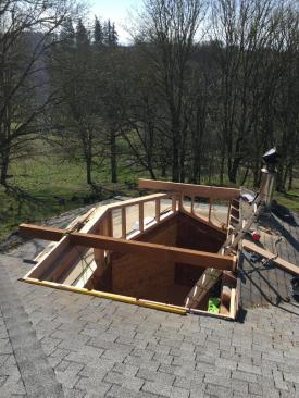
A large hot tub occupied the atrium, so the first order of business was removing the tub and cleaning out the leaves and debris that had collected on the slab supporting the tub. We also demoed a small deck that surrounded the tub and was ledgered to the exterior walls.
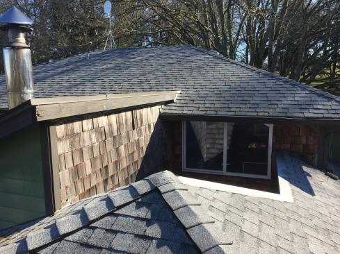
The Oregon home featured an atrium that was surrounded by four walls and open to the sky. The plan was to enclose the atrium to create new living space, and to cap it off with a new 3rd-story reading room surrounded by a deck.
Once we’d removed the windows and the exterior trim from the atrium well, framing the new space was straightforward. We removed and relocated an existing exterior wall on the first floor, which required a new support column in the basement to carry the redistributed loads from the floor system above. We also removed an exterior wall on the second floor, replacing it with a framed entryway into the new office space.
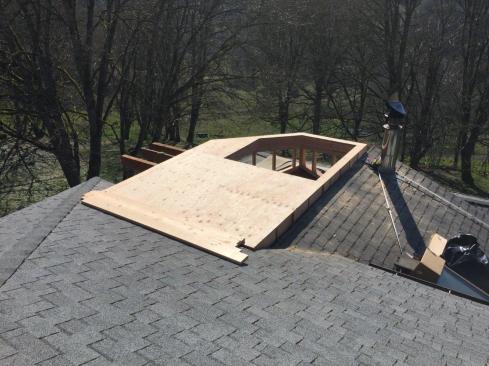
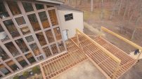
The author’s crew extended the second-floor atrium knee walls to full height (top left), and added cantilevered beams as they framed the new third-story floor system (above) to help support the deck that would surround the new structure (bottom left). The space is capped with a 5-in-12 hip roof (below).
Where one second-floor wall supported an existing shed roof, we cut back the asphalt shingles and roof sheathing as needed to install blocking and new framing to prevent roof joist rotation. Then we extended the knee wall with new 2×6 studs to bring the wall up to full height, tying the studs to the double 2-by knee-wall top plate below with 15-inch-long Simpson Strong-Tie SDWH structural screws driven through DTT1Z hardware installed 24 inches on-center.
On the full-height wall supporting the other rafters, we used a similar approach. To stabilize the rafters, we installed blocking as needed above the double 2-by plate, then installed the new rim joist and floor joists for the third-floor deck. Then we used DTT1Zs to tie the new floor joists to the old wall framing below, driving long, 3/8-inch-diameter lag screws through the DTT1Zs and into the top plate.
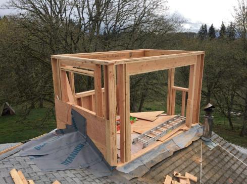
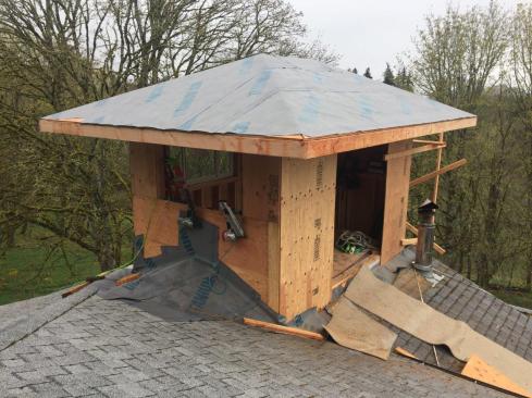
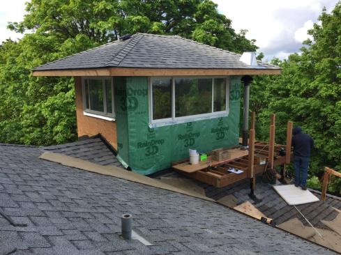
Once the floor system was in place, we framed up the new 2×6 stud walls for the widow’s walk. The new space is capped with a 5-in-12 hip roof.
SkyLift Solution
When we framed the third-level floor system, we installed two cantilevered beams to help support one side of the framing for the U-shaped deck that flanks the widow’s walk. But we also needed to install four columns to support the rest of the deck framing. To ensure that loads from this small deck were properly supported by the roof framing below, we installed four SkyLift #12-HD 12-inch Heavy Duty Designer steel roof risers. These are engineered metal brackets designed to support elevated patio supports and similar structures. In this case, we used the risers to support the beams carrying the deck framing.
Most of the time, SkyLift risers are installed directly on top of the wall plates through access holes cut through the roof sheathing, but in this case, the risers needed to be supported by the roof framing midspan, underneath the deck. After plumbing down from the deck beams once they were installed and opening up the sheathing to verify the exact location of the rafters, we cut 4×6 Doug fir blocks to length to fit between the rafters at each riser location. Then we mounted the blocks to the rafters per the architect’s drawing using 5/16-inch steel angle brackets with 6-inch-tall vertical legs and 3 1/2-inch-wide horizontal legs, through-bolting the brackets to the rafters with 1/2-inch-diameter bolts.
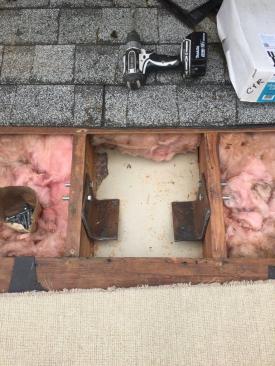
At each SkyLift location, the crew opened up the roof sheathing and drilled holes in the framing for a pair of steel angle brackets.
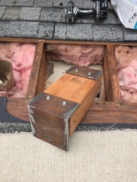
4×6 Doug fir blocks were then cut to fit, and bolted to the steel angles.
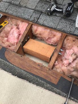
With the blocks mounted to the brackets, the brackets were then through-bolted to the roof framing with 1/2-inch-diameter bolts.
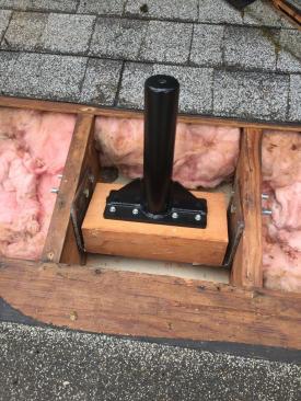
Then the SkyLift riser bases were fastened to the blocks with 1/4-in. x 3 1/2-in. structural screws.
We fastened the riser bases to the support blocks with 1/4-in. x 3 1/2-in. SST SDS structural screws. After patching the roof sheathing and slipping the flashing boots over the risers so that we could reshingle these sections of roofing, we bolted the 3 1/2-inch saddles that hold the beams to the risers.
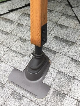
After reinstalling the roof sheathing, workers slipped standard pipe jack flashing boots over the riser bases and patched in the roof shingles. 4×4 PT Doug fir posts were then bolted to the U-shaped saddles that complete the SkyLift riser assembly.

While part of the wrap-around deck is supported by beams bearing on the 4×4 PT Doug fir posts bolted to the SkyLift risers, the deck is also partly supported by the cantilevered beams that were installed as part of the reading room floor system.
The SkyLift risers are connected to the deck framing with 4×4 PT Doug fir posts. At the top of the posts, we reinforced the post-to-beam connections with pairs of Stanley-National heavy-duty 1/4-inch steel decorative corner braces, which we fastened to both the posts and the beams with 1/2-inch-diameter bolts. The longest column is also braced with a diagonal PT 2×4 fastened to the post and deck framing with 3/8-inch-diameter through-bolts.
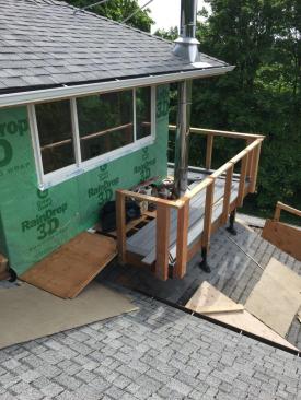
The crew bolted 4×4 clear cedar intermediate guard posts to the framing (above). At the corners, they installed 4×6 posts, then completed the guard rail frame with a 2×4 subrail before beginning installation of the capped composite decking that would complete the project (right).
Finishing Details
We bolted the 2×8 PT deck ledgers to the widow’s walk’s rim joists, spacing the ledger away from the sheathing with 1/2-inch-thick polypropylene Deck2Wall spacers. After hanging the 2×8 deck joists, we reinforced the deck-to-house connection in several locations with pairs of SST DTT2Z lateral load anchors fastened to a deck joist and corresponding floor joist, each pair connected with a 1/2-inch-diameter threaded rod.
We through-bolted clear cedar 4×4 intermediate posts and 4×6 end posts to the rim joists of the deck every 36 inches, reinforcing each post connection with a pair of DTT2Z anchors. In preparation for the cable railing, we installed a 2×4 subrail, reinforcing the corners with SST 55L strap ties, then installed the clear cedar 2×6 top rail.
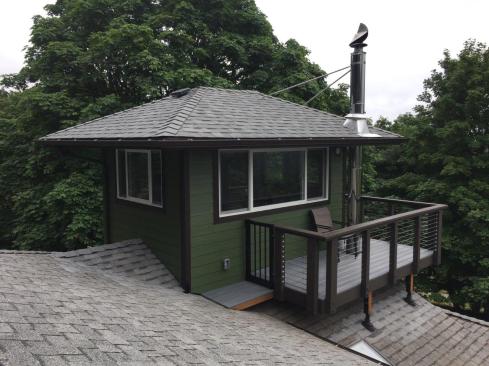
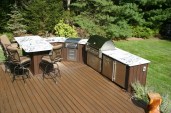
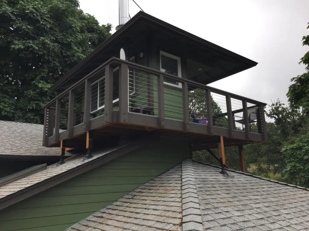
The widow’s walk—a quiet reading room with views of Oregon’s Willamette Valley—and surrounding deck and railing were finished to match the existing house.
After we finished installing Wolf capped composite decking, we completed the Type 316 cable railing install (approximately 2 13/16 inches on-center). Where the end of the deck is close to roof level, we installed an aluminum gate and a short ramp for occasional access (to clean gutters and a metalbestos chimney). After the widow’s walk was trimmed and painted, we stained the deck framing and rail posts to match.
Photos by the author. ❖