Like most structural repair projects, this one involved more preconstruction work and site prep work than actual repair work on site. We started several months before any site work was performed with an inspection of a heavy timber roof beam that supported a section of roof in an old warehouse, which had been converted years before into a condominium apartment complex. This beam was taking a significant amount of the roof’s load, and it appeared from the ground that the timber was rotating. A closer inspection revealed a total beam failure. A core sample was ordered, which confirmed that the interior of the heavy timber had rotted away.
The leaks that initially caused this rot had been taken care of long ago, and by this time, the interior rot was dormant. The beam wouldn’t deteriorate further if it stayed dry, but it was structurally unsound. In an effort to save the homeowners association money, the engineering team weighed leaving the timber in place against the much more involved job of removing and replacing it. For the final design, the engineering team and homeowners association opted to install a new steel beam directly under the existing timber to carry the roof load. This replacement beam would also be designed to pick up the loads on all the purlins that tied into the beam. The purlins themselves were perfectly sound, but we could no longer rely on their connection to the timber beam.
Field Measurements
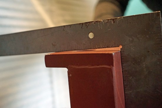
Once we had a design that was feasible and within the client’s budget, we needed to take field measurements so we could order the steel beam. The failed heavy timber was anything other than straight, and the purlins were all at different elevations. One of the columns was also out of plumb by a few degrees.
Using a laser to set a benchmark height, we were able to identify the failed beam’s low point and high point and all the purlin elevations. Once we had these measurements, we could start working on the shop drawings and order the steel.
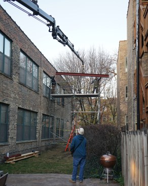
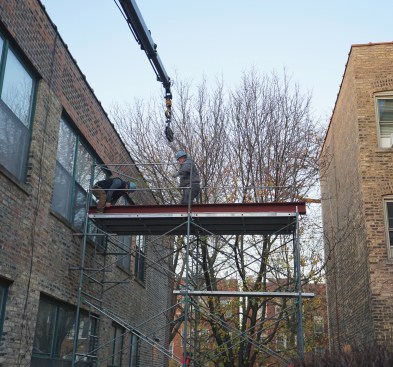
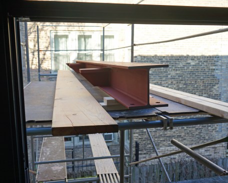

The author’s crew set up scaffolding and craned the replacemen…
Maneuvering the Steel and Prepping the Site
There was no easy way to bring the modified W-beam into the condo unit. We ultimately decided the best course of action would be to bring it in through a window. To accomplish this, we first set up scaffolding outside the unit. This allowed us to set the beam with a crane on the scaffolding so we would be able to roll it in when we were ready for it.
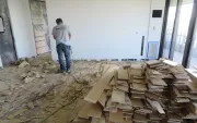
Before we could move the beam into position, some of interior walls around the failed beam had to be demolished. We were responsible for laying out what needed to be demolished for the demo contractor. We also met with the electrician to discuss removing some electric work that was mounted on the failed beam. Once everything was demoed, and the electric was out of the way, we were ready to go.
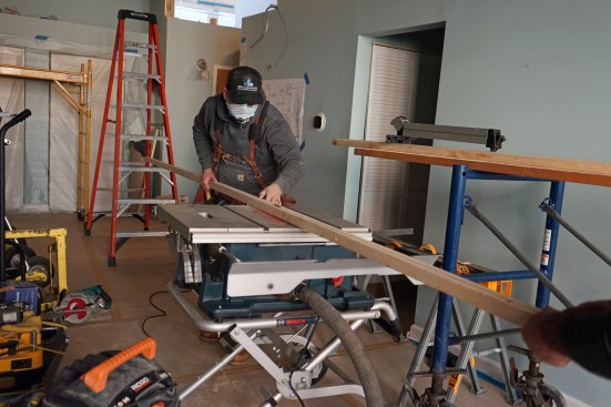
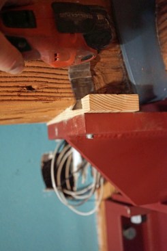
We laid down floor protection and started setting up our shop. The first task was to shim the bottom of the failed beam so when we raised the new steel beam into position, it would sit level. To do this, we set up a laser line tangent to the beam’s low point. Then we measured from the beam to the laser to find the shim heights. Following these measurements, we ripped tapered strips and screwed them to the bottom of the beam.
We now had a flat surface to which we could lift the beam. We rolled the beam off the scaffolding onto the material lifts. We used two Sumner 2118 Series telescoping lifts, which are sized to move through standard door openings and have 5-inch polyurethane casters that roll smoothly. However, the lifts have a fairly wide footprint that can sometimes get in the way of our ladders. After positioning the beam where we wanted it, we set up post shoring, which we clamped to the bottom of the W-beam flange.
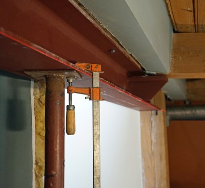
Once the beam was positioned and checked for level with a line l…
Securing the Beam
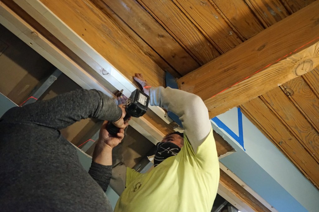
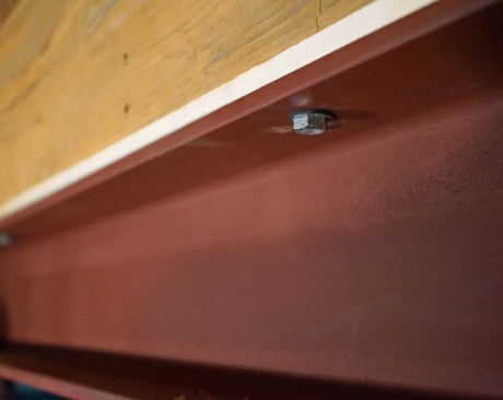
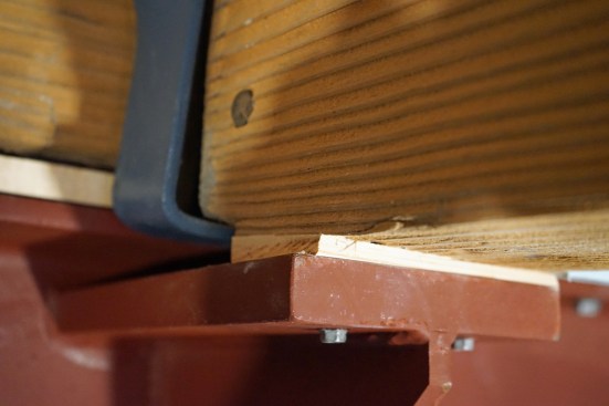
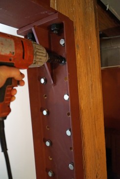
Two post shores were enough to support the beam, but we also secured the beam with lag screws through the beam flange and the leveling strips. This was for positioning only as we completed the next step: shimming between the purlins and the gusseted plates that we had fabricated on the beam.
For this work, we used an angle finder, aligning it to the bottom of the failed beam and in line with the gusseted plates, so we could dial-in to level on the bubble vial. We had to do this in two directions (in line with the new beam and in line with the gusseted plates at a right angle to the beam) to find the compound angle we used to cut the shims. Once the shims were cut, we tapped them into position and trimmed them flush with a multitool.
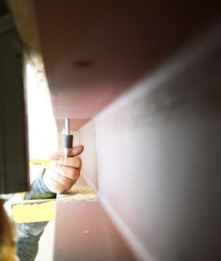
With the beam secured, a crew member lifted one end bracket into…
End Brackets
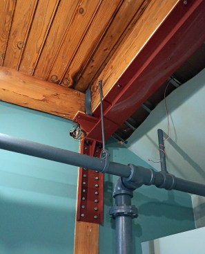
The primary load on the beam is carried by two end brackets, which we call “haunches,” that transfer the load to the existing wood columns. The load on these columns carries all the way down through the structure to complete the load path.
Each bracket was fabricated slightly differently to align with the existing columns, one of which was slightly out of plumb. As shown in the slide show “Installing the Haunches,” the top bearing flange on this bracket was purposefully fabricated out-of-square to accommodate the out-of-plumb column. (This underscores how critical it is to get proper field measurements of existing structures. Good measurements make for accurate shop drawings, which make tricky jobs go much smoother, in my experience.)
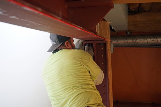
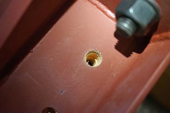
We installed the brackets with lag screws, using a two-step predrill—one bit for the diameter of the shank in the threaded section, and another for the diameter of the shoulder section. When installing these lags, we alternated holes to draw the bracket in uniformly.
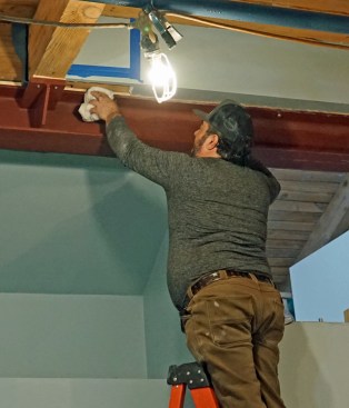
As a final step, we wiped down the beam. Once we were finished, the electrician reinstalled the electrical and a drywall crew patched the wall surfaces to complete the job.