Eaves and rakes that overhang a building’s sidewalls are critical to the life of a building. Shedding rainwater away from siding and trim—especially from door and window sills—can greatly reduce rot, mildew, and a host of other problems that can be caused by water streaming down the face of the building. And aside from the practical considerations, well-proportioned overhanging eaves and rakes can also be an attractive design element.
There are many ways to frame eaves and rakes. My system is straightforward and provides strong, positive attachment of the overhanging elements to the building, as well as solid nailing for the finish materials. I recently built a small outbuilding with a 6-in-12-pitch roof that offers a perfect example for showing the process I use to build eaves and rakes.
Start With the Rafter Tails
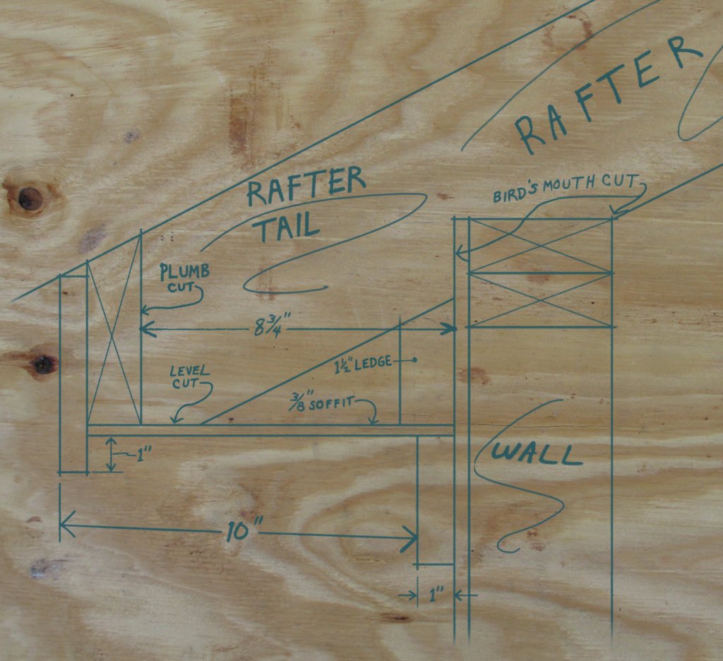
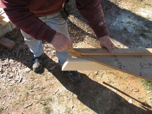
The main component of any eaves detail is the rafter tail—the part of the rafter that extends beyond the exterior wall. To determine exactly what the rafter tail will look like, I always make a full-size drawing on a scrap of plywood of all the eaves elements, including framing and finish materials (see illustration, above).
The first thing I determine on the drawing is the overall width of the eaves. For this project, that was 10 inches from the outside of the frieze board to the outside of the finished fascia. After drawing the wall framing, the sheathing, and the 1-inch-thick frieze, I squared a level line from the outside face of the frieze and marked 10 inches out from there. Aligning the edge of my jig on the mark, I drew a plumb line that represented the outside face of the fascia. From this reference, I marked another plumb line 3/4 inch in for the thickness of the fascia, and 1 1/2 inches in from there for a 2-by subfascia. This established where I would need to make the vertical cut for the rafter tail, which turned out to be 8 3/4 inches from the sheathed wall.
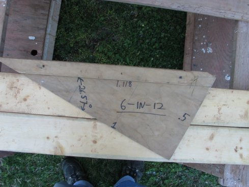
A simple rafter jig helps with laying out the eaves details. The triangle has the plumb line on one leg and the level line on the other, so it is also handy for drawing cutlines. Information such as number of degrees and length of hypotenuse in a base one triangle are also included for reference.
To help with the drawing and with laying out rafters, I used a simple rafter jig that I built on site from a piece of plywood with a factory corner. From that corner, I cut a right triangle at the roof pitch, doubling the rise and run dimensions so the jig could be used for cutting full-size rafters. For this 6-in-12-pitch roof, I made one leg 12 inches and the other 24 inches. After cutting the angle, I attached strips of 1×2 along the hypotenuse on both sides. I also labeled the jig with the pitch and the angle; I save all my jigs and stow them for the next time I need to cut a roof with the same pitch.
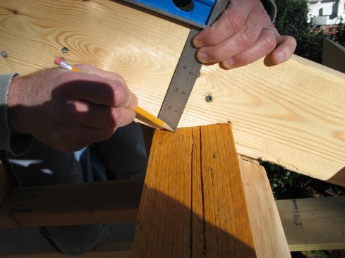
To use the jig, I simply hook the 1×2 to the top edge of the rafter stock and I instantly have both plumb and level edges to scribe to.
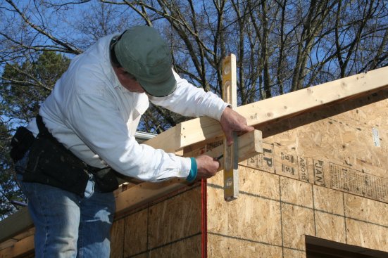
The rafter tails can be shaped on the ground using the rafter jig to lay out the pattern rafter quickly and accurately. But I prefer to cut and install the rafters with just the ridge cut and birdsmouths, leaving the tails long to be cut in place. So after the rafters were nailed in, I measured out from the sheathing the distance—8 3/4 inches—I’d determined for the overhang, and I marked the first and last rafters. I plumbed lines up from those marks and then snapped a chalk line from one end of the roof to the other across the top edges of the rafters. Using that snapped line as a guide would put the rafter tails in an arrow-straight line.
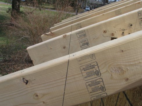
Rafter tails are installed long. Then the plumb cut is measured and marked on the first and last rafters. A chalk line snapped between those marks aligns the plumb cuts on the tails perfectly.
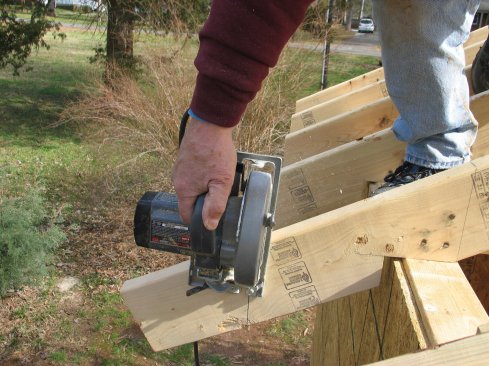
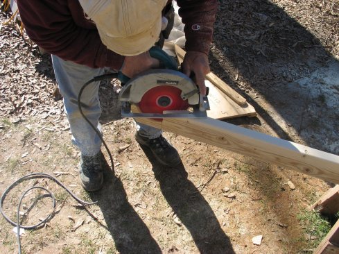
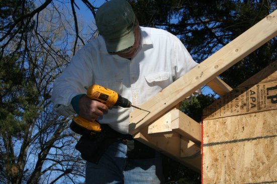
Cutting the rafter tails from above causes the kerf to open naturally as you cut, and it lets the waste fall away harmlessly.
On each rafter, I plumbed a line down from the chalk line using a Hanson Pivot Square set at a 6-in-12 pitch (I could also have used my jig at this point; there just needs to be enough room to align it on the tails). The Pivot Square also provides the angle, which for a 6-in-12 pitch is 26.5 degrees. Then, standing on top of the wall, I cut down each plumb line with a circular saw.
I like to cut the tails from above because the saw kerf opens as the cut nears completion, letting the waste fall harmlessly down and away from the saw.
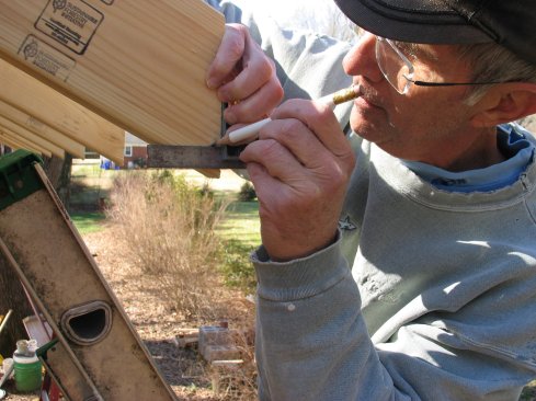
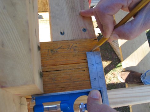
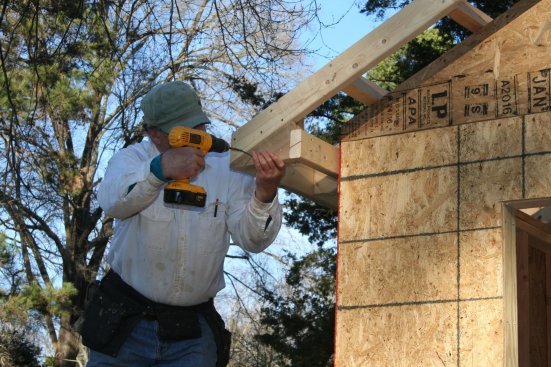
The plumb cuts for these rafters are too long for the fascia, so the height (taken from the full-size drawing) is measured and marked on the end of each tail. A line is then squared over for the level cut.
The plumb cuts on these rafter tails were more than 6 inches long—too long for the 1×6 fascia that I intended to use. To shorten the plumb cut, a level cut along the bottom of each tail was needed. I went back to my full-size drawing and put the top outside edge of the 1×6 fascia in line with the top of the rafter. Then I drew the lower finished surface of the soffit 1 inch up from the bottom of the fascia. (This amount is arbitrary, but a 1-inch overlap has always looked right to me). The 3/8-inch thickness of the soffit material came next. That line also indicated the bottom of the subfascia.
The top of the 2×6 subfascia was beveled to continue the line of the 6-in-12 roof pitch. To make sure the level cut of the rafter tails didn’t interfere with the soffit installation, I drew the cut 5 1/4 inches from the short point of the plumb cut to provide plenty of clearance. After measuring down that distance on the plumb cut of every rafter, I marked the level cut square to the plumb cut and made the cuts using a circular saw.
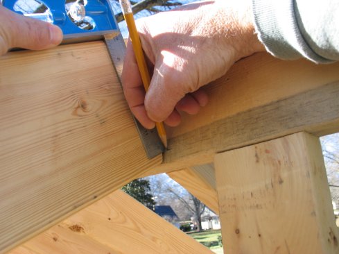
After the subfascia is installed, a line is squared over to the sheathing to locate the ledger for attaching the soffit.
The ledger is left long and will be cut to length when the returns are built. Notches under the rafters allow the ledger stock to be full-dimension on the ends to better support the return framing.
Finish the Eaves Framing
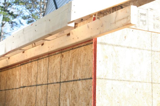
After ripping the top of the subfascia with a circular saw set to 26.5 degrees, I flushed the top ripped edge with the top of the plumb cut on the rafters and screwed the subfascia to the rafter tails. On both ends of the roof, I let the subfascia run out beyond the anticipated width of the rakes. This well-anchored cantilever will provide firm support to the lower end of the barge rafter, as well as supporting the return.
Once the subfascia was attached, I squared over from the bottom of the board and marked a line level on the wall sheathing at both ends of the wall. I snapped a chalk line and then fastened a 2-by ledger to the wall with the bottom edge on the line. On this project, I notched the ledger to fit below the rafters so that the ends where the return framing would be attached would have the full stock dimension. As with the subfascia, I ran the ledger out past the anticipated width of the rake on both ends of the building. The cantilevered section of the ledger will support the rake returns.
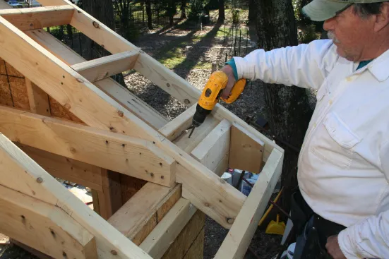
Blocks made from 2x4s attach to the subfascia and to the ledger to support the soffit material and soffit vent.
Because I planned to use continuous eaves vent on this project, I added cross blocks to support the inside edges of the soffit material, as well as the vent itself. I cut the cross blocks to fit and installed them next to the rafter tails. Installing the blocks before the finished fascia lets me nail through the subfascia and into the ends of the cross blocks. These blocks can be installed at any point after the subfascia and ledger are installed; on this project, I installed them after the barge rafter had been installed.
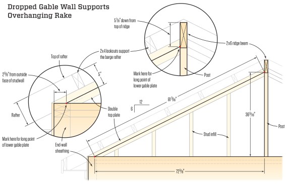
The triangular part of the gable wall is built after the rafters are installed. The diagonal plates are 3 1/2 inches down from the tops of the rafters to support 2×4 lookouts for framing the rake. After the end points of the plates are located, the length is found using a base-1 triangle for a 6-in-12 pitch where the hypotenuse is 1.118 times the length of the base. After the gable is framed, lookouts extend from the first rafter inside the gable wall out over the plates to support the overhanging barge rafter.
Framing a Dropped Gable Wall
One of the keys to framing the rake with my system is building a “dropped” gable-end wall, the top of which is 3 1/2 inches below the tops of the rafters. Then, after the wall is built, I install 2×4 “lookouts”—blocks that extend from the first rafter in from the end of the building, over the dropped gable, and out to a barge rafter to form the overhanging rake (see Dropped Gable Wall Supports Overhanging Rake, above).
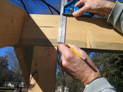
To find the long points for the lower plate of the dropped gable, set a square to 5 inches (3 1/2 inches for the lookouts and 1 1/2 inches for the top plate). Slide the square down the rafter and mark where it touches the top of the wall.
Measure and mark that distance in at the end of the wall. That mark is where the bottom long point of the gable plate will land.
To save time, I added the triangular “gable” part of the wall after the lower walls were built and raised. I framed the dropped gable with a double top plate, and I began by finding the end positions of the lower top plate. The top edge of that plate was 5 inches below the tops of the rafters. So I set my combination square to 5 inches and slid the fence down a rafter until the blade touched the top of the wall plate. I marked that point and then measured from it to the outside face of the wall (2 5/8 inches). At the end of the side wall, I measured in 2 5/8 inches, which marked the bottom long point of the lower plate for the dropped gable.
At the top of the rafter, slide the square up to the ridge and mark where the blade touches.
Mark that distance down from the top of the ridge. This is where the upper long point of the gable plate will land.
To find the upper long point of that plate, I slid the combination square up the rafter until the blade touched the ridge. After marking and measuring that point (5 1/8 inches down from the top of the ridge), I marked that distance along the ridge above the end wall. This line marked the top long point of the lower gable plate.
Before building the gable, I marked and cut the section of the ridge that extends out for extra support at the top of the overhanging rake, which was probably overkill given all the lookouts holding the barge rafter. To cut the ridge, I plumbed up from the wall below and then measured out 10 1/2 inches for the overhang plus the sheathing, and marked the vertical cut. For the horizontal cut, I set my combination square to 3 1/2 inches (the width of the barge rafter) and slid it up one of the rafters to the ridge. As before, I marked where the blade of the square touched the ridge and measured from the top of the ridge down to that mark. On the overhanging part of the ridge, I marked and cut a level line at that distance, minus 1/2 inch to allow the slope of the barge rafter to continue to the peak.
To build the gable, I installed a plumb post from the top plate of the end wall up to the ridge. I confirmed the gable layout by measuring up the post to the plate layout point marked on the ridge, and then out from the post to the layout point on the plate of the end wall. Because the rise should be half the run in a 6-in-12 layout, those measurements confirmed that the layout was correct.
The next step is to determine the length of the lower gable plate, long-point to long-point. To do this, I took the number I’d written on my rafter jig for the hypotenuse of a base-1 triangle.
This number is easy to find using an old-fashioned framing square. Under the “6” on the square is the number 13.42, or the length of a rafter per foot of run. I divided 13.42 by 12 inches to come up with 1.118 when the length of the base is 1. Then I simply multiplied the length of the base (72 5/8, or 72.625, inches) by 1.118, which equaled 81.195 (or 81 3/16) inches, or the length of the bottom gable plate, long-point to long-point.
For the lower long point on the gable plate, mark the pitch angle on one end using the rafter jig. Square across the stock and mark both edges.
To cut the acute angle, make the cut from both sides of the plate stock. When finished cutting, smooth the cut surface wth a belt sander. Measure and cut the plate to length by making a simple plumb cut at the top.
On both edges of a 2×4, I laid out matching 63.5-degree cuts (the complementary angle of a 6-in-12 pitch) using the level edge of my rafter jig. This acute angle formed the long point at the low end of the gable plate. After cutting along both of these lines with a circular saw, I smoothed the cut with a belt sander. Then I pulled the plate measurement (81 3/16 inches) from the long point of this cut to mark the long point of the plumb cut, which I made on a miter saw.
After putting in the studs for the dropped gable, cut and install the second plate.
I aligned the ends of this plate with the marks on the ridge and end-wall plate and then fastened the plate in place at both ends. After checking to make sure the plate was straight, I laid out and installed studs, keeping them in line with the studs of the wall below. I made the angled cuts for the top of each stud with the miter saw set to 26.5 degrees and nailed through the plate to attach them at the tops. To finish framing the dropped gable, I cut and installed a second top plate over the lower one.

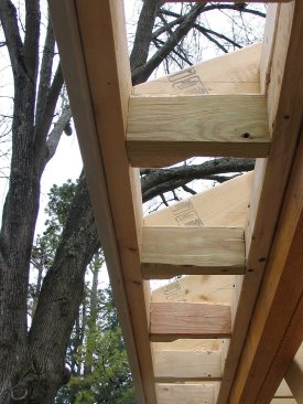
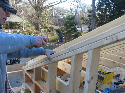
2×4 lookouts sit on top of the dropped gable, with the ends left long. They nail to the first rafter and then cantilever out to support the barge rafter. A snapped line across the ends of the lookouts ensures that the barge rafter will be perfectly straight.
Building the Rake
After measuring and marking the cantilevered portion of the subfascia 8 1/2 inches from the gable wall, I cut it in place with a circular saw. On the gable plate, I laid out the locations of the 2×4 lookouts at 16 inches on-center. I cut and installed the lookouts a little long and then snapped a line across their top edges 8 1/2 inches out from the wall. Again, this snapped line put the ends of the lookouts in a perfectly straight line. After squaring down from the marks, I cut the lookouts in place with a circular saw.
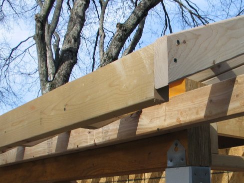
After the ends of the lookouts are cut, the barge rafter is installed and the end is cut flush with the subfascia.
With my rafter jig, I laid out and plumb-cut the top of the barge rafter, leaving the bottom uncut for now. To install the barge rafter, I pushed the top end tight against the ridge and ran it past the ends of the lookouts and the subfascia. After nailing the barge rafter at all those points, I cut the bottom end flush with the outside face of the subfascia.
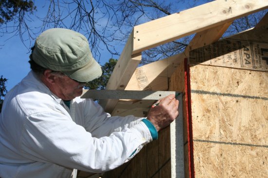
Framing the Return
The ledger that was left extending past the rake provided support for the return framing. To cut it even with the barge rafter, I plumbed down from the face of the rafter with a small level, and marked a plumb line on the ledger.
Before framing the return, plumb down from the barge rafter and mark where the end of the ledger will be cut.
Screw a 2-by block to the back of the barge rafter and to the ledger.
The block provides attachment for the triangular piece that fills in the end of the return. The face stays in plane with the barge rafter and the bottom edge lines up with the blocking for the soffit.
After cutting the ledger to length, I built the return with scraps of 2-by material. I didn’t waste time trying to join the materials edge-to-edge. Instead, I built the return using nailer blocks. I began by cutting a scrap of 2×6 with a 26.5-degree miter at one end. I held this piece vertically, with the miter lined up with the top inside edge of the barge rafter and one edge butted against the ledger, and I marked the bottom edge. After cutting the block to length, I screwed it to the inside of the barge rafter. Using my rafter jig, I laid out and cut a triangular piece that fit under the rafter and butted against the side of the ledger. This piece screwed to the 2×6 block and built out the surface of the return in plane with the barge rafter.
Before the roof sheathing goes on, the open framing provides easy access for attaching the return blocking and the nailers for the rake soffit.
The last pieces to go in were nailing blocks above the ledger for the back of the return, and at the bottom edge of the soffit for attaching the rake. With no sheathing on the roof, there was plenty of access for an easy installation from above and behind the return.
Photos by John Carroll