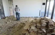
I didn’t even know what a kickout flashing was until the second half of my building career. After seeing and repairing a couple of rotted walls below eaves overhangs, I realized that we needed a different approach to accepted flashing practices.
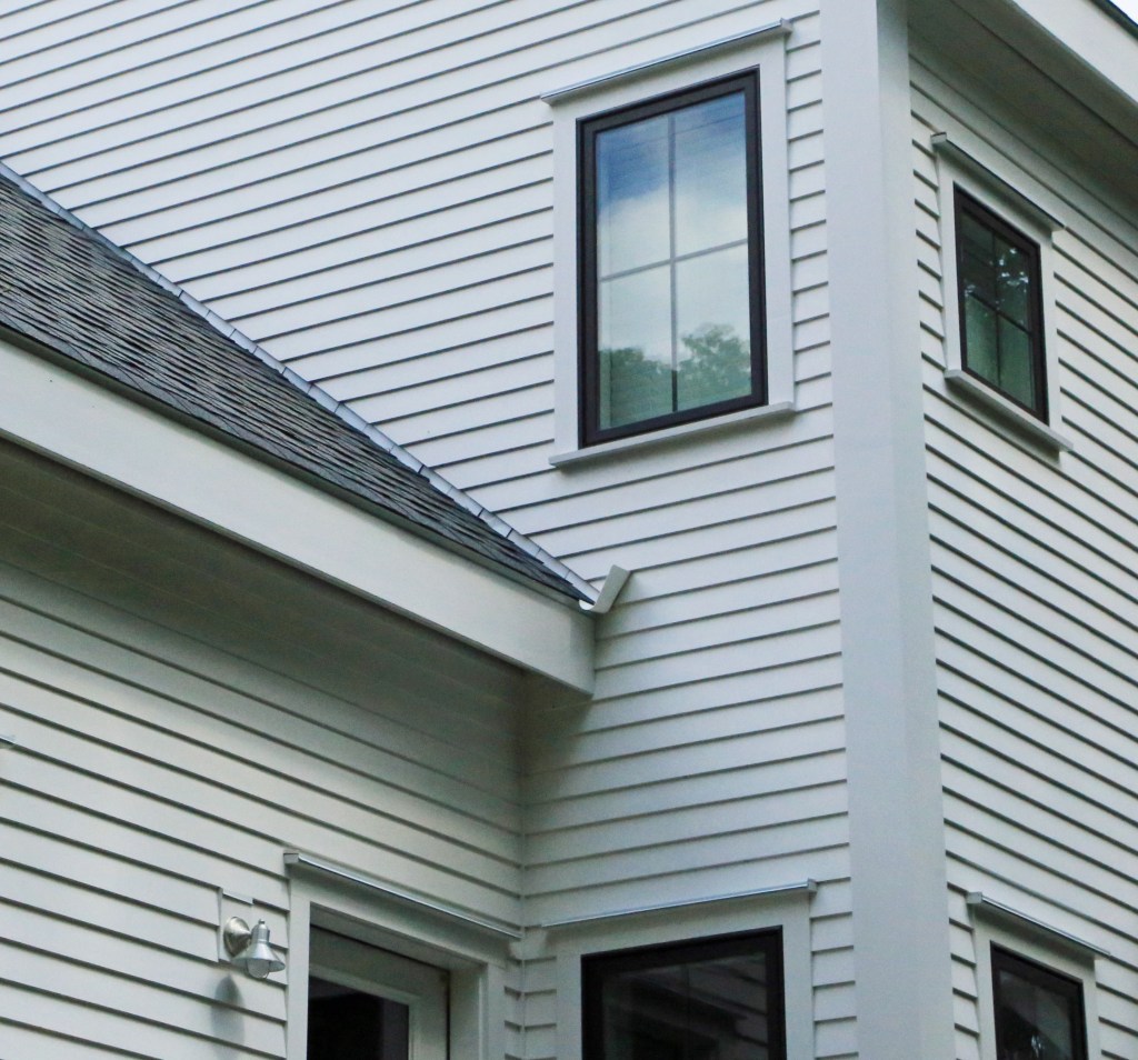
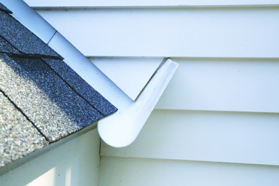
In the simplest terms, a kickout flashing is a special type of flashing installed at the edge of a roof where the eaves meets a wall. A common example is where the eaves of a garage roof meets the wall of a two-story home. The wall leg of a kickout flashing extends out from the wall, protruding away from the siding and directing roof runoff away from the wall.
Kickouts in the code. Kickout flashings have been required by the International Residential Code (IRC) since 2009, yet I’ve rarely seen them installed on new homes and additions. Part of that might be the original awkward language that didn’t even include the term “kickout flashing.” In the 2012 IRC, Section R903.2.1, Locations, the language was changed to be clearer: “A flashing shall be installed to divert the water away from where the eave of a sloped roof intersects a vertical sidewall.” Unfortunately, neither the IRC nor the code commentary on that section includes an illustration of the flashing.
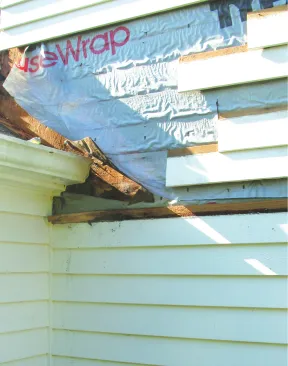
Kickout flashing has been required by code for more than 10 years, but the author still finds instances where it wasn’t installed—with predictable results.
Even though the code and good building principles call for us to install kickout flashing, it is often overlooked (or ignored) by builders, roofers, siding installers, and code inspectors. Perhaps that’s because the requirement is fairly recent and the need for kickout flashing along with the method to install it properly isn’t knowledge that has been passed down. Or maybe it’s because the installation process involves different trades at different stages of construction, and no single person accepts responsibility for the detail. And then there are aesthetic concerns: Those turned-out flashing legs aren’t very attractive, so contractors may opt not to install them.
Good kickout flashing detailing is hard to execute—not because the process is difficult, but because it involves an intersection where multiple trades have a hand in the installation. To be effective, kickout flashing has to be layered with the framing, weather-resistive barrier (WRB), trim, roofing, and siding in a way that blocks water from getting into the wall assembly and redirects that water to where it can safely drain away. The sequence I follow is a little redundant and quite detailed in the application of water-shedding layers. My cautious approach is informed by the numerous repairs I’ve done—even some where kickout flashings had been installed, but water had still leaked behind the flashing and the WRB.
Start with the framing. I will describe the process with the WRB already installed, but I will also note where modifications can be made for other circumstances; for instance, if the WRB is to be installed later or if the house has a sheathing-integrated WRB such as the Zip System.
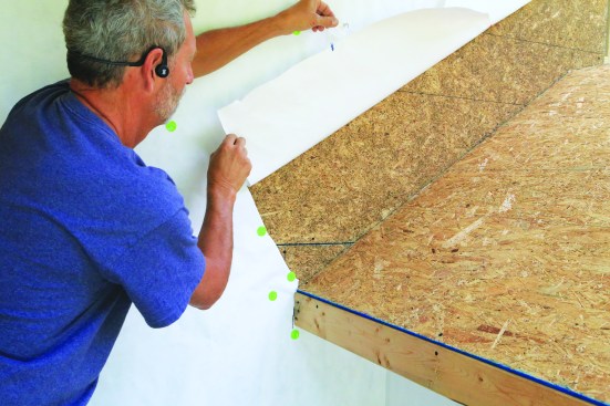
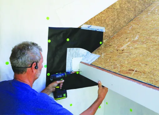
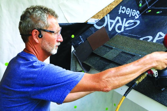
The first step to installing the flashing is cutting and lifting a flap of WRB to access the sheathing at the roof-wall intersection.
Some of the waterproofing layers that precede the kickout flashing require solid backing along the fascia plane. If a subfascia has not been installed, fasten a block in the rafter or truss bay closest to the wall.
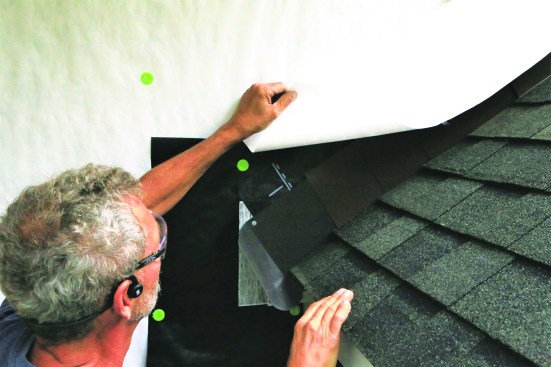
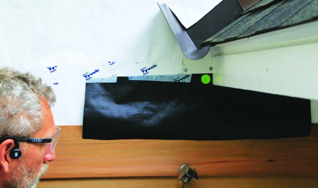
Start by cutting a 9-inch-wide (or wider) flap in the WRB, and fold it up the wall. Next, slide a 2-foot-square piece of WRB sheet over the main WRB at the eaves edge. Ideally, I slip it a couple of inches behind the rafter or truss tail, or just notch it to fit around the subfascia and roof. (If the main WRB isn’t installed yet or sheathing-integrated WRB is used, apply the square piece of WRB to the sheathing surface.) Position the top of the piece about a foot above the eaves and cap-staple it to the wall, leaving the bottom of the sheet loose to integrate with the siding later. (When installing the square WRB piece over sheathing-integrated WRB, seal the top edge to the sheathing with self-adhering flashing (SAF) or with fluid-applied flashing.)
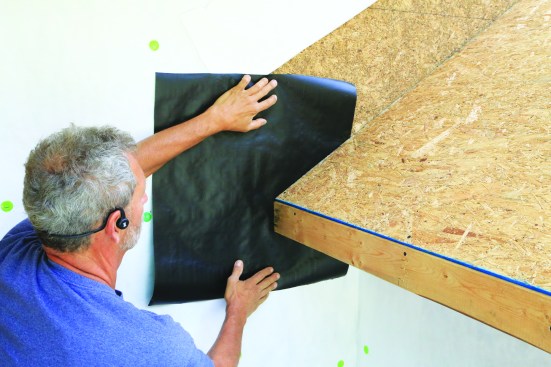
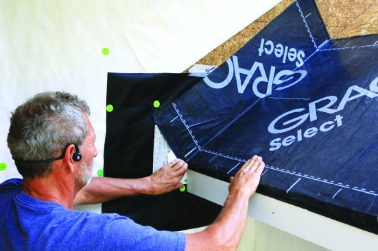
Subfascia or solid blocking provides backing for the flashing layers. A square of WRB (black was used in the photos for clarity) slides behind the eaves-wall intersection.
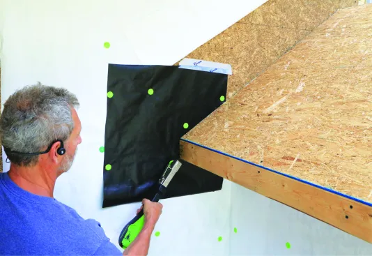
The WRB is stapled into place.
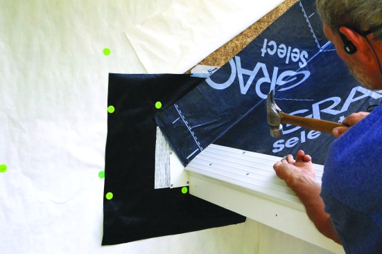
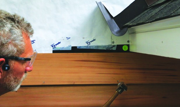
Seal the 3D corner. Next, using a piece of flexible SAF, I preflash the intersection of the subfascia, the square piece of WRB, and the roof sheathing. The SAF is less prone to damage and leaking than the sheet of WRB beneath, and the tape seals the three-dimensional connection in case the kickout flashing is ever damaged.
Flexible flashing tape bridges the intersecting surfaces.
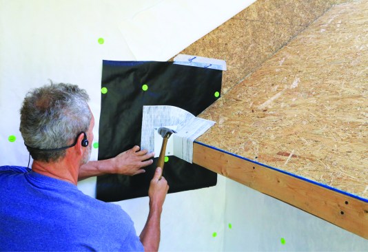
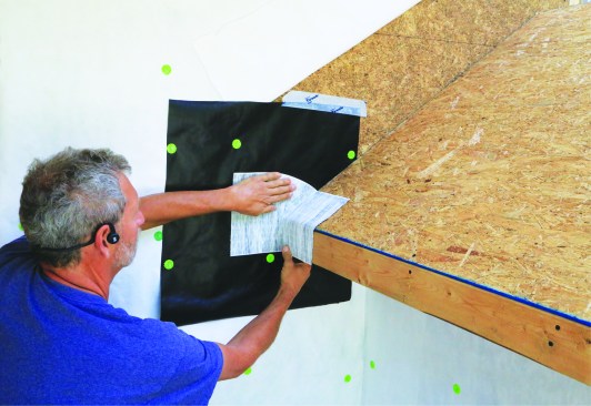
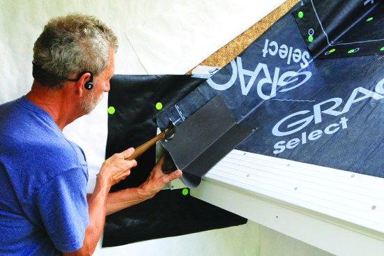
Metal flashing protects the tape.
The finished fascia board can be installed at this point, but for another layer of protection, I often install a metal corner flashing over the flexible SAF for good measure. The metal anchors the tape in place and shields it from exposure and view if there is any gap between the siding and fascia. The fascia can butt up to the corner.
The finished fascia goes in next.
In cold climates, ice barrier laps over the fascia and up the wall.
For cold climates, run the ice-barrier membrane along the eaves edge so that it overlaps and seals the top of the fascia board and extends 6 to 8 inches up the sidewall. In climates where an ice-barrier sheet isn’t typically installed, I recommend applying a 4-foot-long by 12-inch or wider strip of self-adhering membrane between the wall and roof sheathing. The drip edge goes in next over the ice barrier along the eaves edge. Be careful to leave a 1/4-inch gap at the end of the drip edge so that it doesn’t exert any pressure on—and cut into—the upturned ice barrier or membrane strip.
After the ice-dam protection is installed, the drip edge goes in. Be sure to leave it 1/4 inch short of the wall.
Flashing and roofing. At this point, the first piece of step flashing—the kickout flashing—can be installed. Premade kickout flashing is widely available, or it can be fabricated from a large piece of step flashing. I prefer using manufactured plastic kickout flashing such as DryFlekt, which has a scupper formed to direct water into a gutter. Plus, I can trim the turn-out leg to any length. Because the turn-out leg has to extend out beyond the siding, I choose a flashing color that is close to the color of the siding.
Next, the kickout flashing—which is also the first piece of step flashing—is nailed in place.
The roofer can then install the shingles and the rest of the step flashing, continuing up the roof.
Be sure that the turn-out leg is deep enough to extend through any exterior insulation and rainscreen space and then go beyond the surface of the siding by at least 1/2 inch. I align the inside heel of the kickout flashing about 1/2 inch lower than the bottom of the drip edge and fasten the flashing to the roof and wall. With the kickout flashing positioned, the roofing and regular step or continuous flashing can be installed along the sidewall.
Drop the flap of WRB back down over the step flashing along the roof-wall intersection.
Buttoning up. Once the roofing is installed, the flap of WRB taped up earlier can drop down over the wall legs of the step and kickout flashings. To counterflash the top of the square piece of WRB, another piece of WRB can be inserted into a slice in the main sheet of WRB covering the wall. Trim the counterflashing piece of WRB around the kickout flashing and fully tape it along the top and sides. At the bottom, leave gaps in the tape so any water that might get to the inner layers of WRB can weep out.
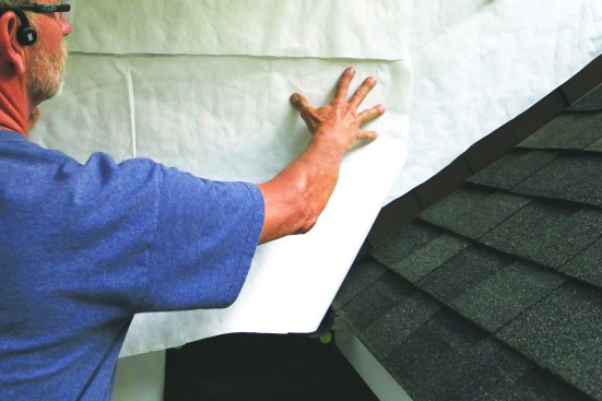
Slit the WRB and slide an additional piece of WRB into the slit to protect the square (black) piece installed earlier.
Anchor the top and sides of this last piece of WRB, sealing it to the main WRB. Leave gaps in the tape at the bottom to allow any water to escape.
If you prefer counterflashing the kickout and step flashings with a strip of SAF or fluid-applied flashing, do that before lowering the WRB flap. This step is often done when flashing to a sheathing-integrated WRB system. If the main WRB is applied after the kickout flashing is installed, it can be applied over the top of the flashing and over the square piece of WRB, with the bottom edge of the square lapped over a sheet of WRB below.
Where the WRB is cut to fit around the top of the turn-out leg of the kickout flashing, there is always a risk of water leaking behind the flashing. And it’s also possible for water rushing down the roof to hit the turn-out leg and to push upwards behind the counterflashing piece of WRB. This is where the square piece of WRB applied earlier does its duty, backing up the weak spot in the flashing system. In the event that any water does get behind the kickout flashing or in the joint where siding fits around the downhill side of the turn-out leg, that water is blocked from reaching the wall sheathing or main sheet of WRB by the square piece.
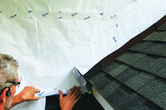
As the siding is installed, the bottom edge of the square WRB piece laps over the siding course just below the eaves.
When the next course goes in, the WRB is trimmed at the bottom of the course.
When a rainscreen space is used behind the cladding, the bottom edge of the square piece can be left on top of the primary WRB sheet, and any water blocked by the WRB piece can freely drain and dry in the vent space. When the siding is applied in direct contact with the WRB, the risk of damage to the siding is higher. To provide an exit for the water, I let the loose bottom edge of the square piece of WRB lap over the top of the siding course, trimming it at the exposure line of the overlying course. To prevent water from being trapped by the overlying course, I tap in a couple of toothpick-sized slivers of wood or plastic between the siding courses to leave a weep gap.
Slots or notches in the siding allow it to fit around the kickout flashing. The layers behind the flashing should protect against any water that might get through.
The cladding has to be cut or notched around the turn-out leg of the kickout. Some installers balk at cutting a big notch in the siding, with worries about leaks. But I consider this to be a transition spot and there’s no getting around having a small gap. I think of it like any other butt joint we install in a cladding system (at the corner boards, window trim, or joints between lengths of siding), which underscores the importance of the layers of WRB beneath the kickout flashing as well as providing an exit for any water.
The turn-out leg of a kickout flashing needs to extend only slightly proud of the siding surface to do its job. Manufactured models have extended legs to use with EIFS, exterior continuous insulation, and siding of varying thicknesses. The manufacturer’s intention is for the installer to trim the leg to whatever length is desired. I typically leave the full leg intact or trim the leg diagonally from the scupper up to the top about 1/2 inch away from the siding. This reduces the leg projection but still leaves the scupper portion at the bottom to direct water into the gutter and away from the wall.
Photos by Mike Guertin