I’m a framer on eastern Long Island. My brother, Fred Jr., and I build a half-dozen custom homes each year, typically 5,000 square feet or larger. While Fred rides herd on the business end of things, I direct the field crew in a hands-on capacity. Last year, we began building a gambrel-roof, shingle-style home that features a two-and-a-half-story turret, 12 feet in diameter and about 32 feet high, not including the rooftop finial. The turret projects from the front elevation and encloses a stairwell with semicircular, mid-level landings between floors. The half-round tower opens into the first and second floors on the inside, but it becomes full-round construction where it penetrates the roof. In this article, I’ll explain how I tackled this complicated piece of framing.
Fred worked with the foundation sub to stake out the turret’s footing and foundation, using a nail to pinpoint the turret location and the center of its radius. From this pivot point, he swung a tape measure to locate the center of a 24-inch-wide poured concrete footing. He later used a trammel stick to swing the outer radius of the foundation wall onto the footing, using the point of a nail to scratch the green concrete. The foundation sub used 6-inch-wide panels to form the wall in a faceted curve.
Circular Plates
The portion of the turret that projected from the building’s facade was a little less than a half circle. Accordingly, we needed a semicircular mudsill and several half-round wall plates to frame the outer walls of the turret. We made the sill and wall plates by laminating a double layer of 3/4-inch plywood. For the mudsill, we used pressure-treated southern yellow pine plywood; the rest of the plates were made from fir cdx.
We cleared a space on the subfloor, laid down a surface of clean plywood to work on, and I used a trammel to draw a full 12-foot-diameter circle to guide the assembly. The plates had to be made from several shorter segments of plywood; we were able to cut about five segments per 4×8-foot sheet. I used two marking points on the trammel, one at the 6-foot radius and the other 5 1/2 inches back, to make a nominal 2×6 plate. Although the cuts were curved, the radius was wide enough that we could make the cuts with a circular saw. Each layer required five or six segments to make a complete ring. We assembled full ring plates, then cut most of them into half-circles for use in the lower sections of the turret. We set aside four full circles with which to frame the section of the turret above the roofline as well as the bell-shaped turret roof. We also cut enough segments to fabricate curved window headers.
Wall framing began directly on top of the pressure-treated plywood mudsill, which was installed as usual over sill sealer and anchor bolts. The 2×6 studs were laid out radially around the sill every 6 inches on-center, measured along the outside perimeter.
We framed the turret platform-style, in three levels. The stacked plates and shorter stud lengths provided more stiffness than balloon framing.
The top plate of the second wall section stopped flush with the second-story ceiling joists. Above that, the framing went fully round where it projected through the roof.
We framed the second wall section with its top plate flush with the top of the ceiling joists over the second floor. Above that level, the turret framing projected above the roofline and became fully round. We framed the ceiling openings square as in a conventional stairwell and added diagonal framing to round off the corners.
The close radial layout created tight stud spacing on the interior side, which was an advantage for drywall application but made for a labor-intensive insulation job. (We used R-19 unfaced fiberglass batts, each batt carefully cut and stuffed to fill the bays’ flared contours.)
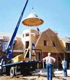
The turret section above the roof stood about 6 feet high. We framed it as a unit, on the garage slab, between two full-round plates, and lifted it into place with our JCD Load-All, an all-terrain forklift.