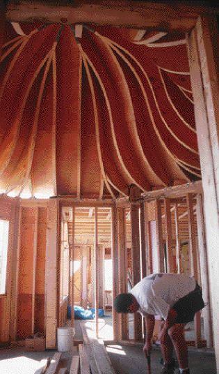
Last summer, contractor Scott Babcock asked me to frame an eight-sided, bell-curve cupola roof as part of a large home he was building. Given a choice, I’ll take roof framing over any other project, and a roof like this one doesn’t come along every day. I jumped at the chance.
The nearly 15-foot-diameter roof would cap a three-story “turret” situated at the ell between the two major wings of the shingle-style home. Considering the complexity of the framing job and the elevation — about 30 feet above grade — we decided to frame the roof on the ground and lift it into place with a crane as a unit. While I finished up another project, I asked Scott to provide me with a temporary, dead-level, 16-foot-square platform on which to build the roof in the yard.
Sketchy Plans
The plans weren’t exactly generous with detail. The architect provided a section drawing of the rafter profile, which featured an ogee curve on the exterior side and a straight interior line to be framed as an open, cathedral-style ceiling. The roof framing plan outlined a simple scheme of eight hip rafters converging at a common center, with a “common” rafter and a pair of jacks filling in each plane of the roof. The common rafters were shown landing against an octagonal “ring” of blocking between the hips near the peak, to minimize the convergence of framing members at the actual center (see Figure 1). Little additional information was provided, which was fine with me. In a situation like this, I’d rather begin with a clean slate than reverse-engineer someone else’s framing vision. I determined the pitch of the roof from the architect’s drawing of the interior ceiling. It worked out to around 13-in-12.
Figure 1.The architect’s plan presented an octagonal framing scheme of eight hip rafters bridged by a ring of blocks that would support a centered common rafter. The author replaced the ring blocking and instead added common jacks.
Dimension check. To accurately map out the plate on my temporary work surface, I carefully checked the supporting wall framing for level, plumb, and dimensional uniformity (see “Determining the Sides of an Octagon,” below). The wall sections were within 1/8 inch of each other in length — close enough — but they needed a little tweaking for plumb. I made the necessary adjustments and added temporary interior bracing to hold the lines firm. Four of the eight supporting walls were interior partitions, three were exterior walls, and one was partially interior and partially exterior. The main roofs met in a complex junction of valleys, gables, and crickets behind the turret, supported in part by a steel girder from which I’d have to face-hang one section of rafters. For the time being, the main roof framing surrounding the turret had been left incomplete, to be filled in after placing the octagon. Several framing features would affect the placement of the preassembled roof, and I made countless trips from the ground, up three flights to the top floor to check and recheck various details. Tiring as it was, the time was well spent. I was determined to drop the roof neatly into place on the first try, rather than end up remodeling the heavy structure as it dangled above my head from the crane’s cable.
Determining the Sides of an Octagon |
When I was called in to frame this octagonal roof, the walls were already standing. Because the plan was to build the roof on the ground and lift it into place, I needed to check the accuracy of the wall plates so that I could duplicate them on the ground. I used an approach that involved some simple trig. 1. First, I measured across the octagon to determine the total roof span: 14 ft. 10 3/4 in. Dividing this in half gave me the run of the common rafters: 7 ft. 5 3/8 in. (89.375 in.). In plan view, the common rafter run is one side of a right triangle. The other side is half the wall plate; the hip rafter is the hypotenuse. If you know one side of a right triangle and one angle, you can use trig to solve for the rest. 2. The hips of an octagonal roof form eight 45-degree angles. The angle between the hip and the common is half that, or 22.5 degrees. 360 degrees ÷ 8 = 45 degrees 45 ÷ 2 = 22.5 degrees 3. I plugged the angle and the side — the common rafter run — into the most basic trig function: tan of angle = opp ÷ adj or in this case: .4142 = X in. ÷ 89.375 in. Rearranging the numbers, .4142 x 89.375 = X = 37.02 in. 4. Since half the plate length is 37.02 in., the full plate length is 37.02 x 2 = 74.04, or 74 1/32 inches. |