Last year, our company was hired to remodel the 24-by-30-foot kitchen ell of a 150-year old Vermont home. The owners wanted the renovation to retain the house’s vintage look while addressing some rather serious defects in the structure.
The second-floor living space of the balloon-framed ell was in good condition and definitely worth saving, as was the beautiful historic slate roof with fine period trim. The first floor, though, was in bad shape: Half the joists had previously been shimmed several inches, creating in effect two separate floor decks, and the entire floor sagged and bounced. We first considered removing the framing and pouring a new radiant slab within the existing stone foundation walls. But on further investigation, it became clear that this would be at best a Band-Aid approach. Justifying the kind of investment the clients wanted to make in their new kitchen would require replacing the old foundation and first-floor framing.
The next order of business was to remove the siding and plaster so we could see what condition the framing was in. But before starting demolition, we established a benchmark elevation on the ell and transferred it to the barn next to the house. We figured that the upper floor would drop slightly as we worked, and we wanted to be able to return it to its original position.
After removing the finishes and exposing the framing, we discovered that a previous builder had shimmed the second-story floor joists to level the floor in the upstairs bedroom over the kitchen area. While this created a flat floor, it left almost 4 inches of sag on the bottom of the joists. It was clear we would have to take pains to create a flat ceiling in the new kitchen.
A Plan for Supporting the Roof
How to hold up the second story while building the new foundation underneath was the big question. We first considered using steel I-beams supported on timbers stacked outside the foundation area. We abandoned this idea when the excavator pointed out how massively tall the cribs would have to be; plus, we knew they would be a pain to work around. We also thought about removing and replacing the foundation in short sections, working our way around the perimeter, but rejected this as too time-consuming.
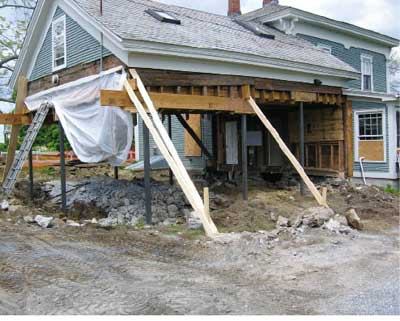
Then, in a meeting with the excavator and concrete sub, we came up with a plan: We would first reinforce the second floor with a grid of LVL beams supported by steel columns; next, remove the framing and stone foundation; then form and pour a new footing and foundation, encapsulating the steel posts in the concrete.
We calculated the approximate weight of the roof and floor — the dead load we’d have to support while the new foundation was built — and had the lumberyard size the LVLs we would use. The idea was to carry all the second-floor loads to the exterior walls and from there to the ground with as few posts as possible. With no temporary shoring to work around in the middle of the ell, the excavator would have an easier time digging out the crawlspace. After the new foundation was placed, we would frame new walls and cut off the steel columns at the level of the rim joist. The LVL grid would remain in place to support the new ceiling and would also serve to reinforce the sagging joists above.
Installing the Ceiling Grid
We located the lowest point of the sagging floor joists and snapped a line on the inside face of the exterior wall studs at that elevation. This marked the top of the LVL grid members. The first piece we installed was a 14-inch LVL beam that runs across the width of the ell about 12 feet from the gable end. This LVL was in line with the wall that would be built later between the new mudroom and kitchen. For now, we ran the beam long; we would cut it flush later after supporting it on the new framing. It broke the ceiling space into two sections, cutting the span of the new ceiling members on either side. Later, when we framed the mudroom wall, we would place a post under the beam to transfer the ceiling and second-floor loads to the new crawlspace girder and on to the ground.
We next attached a 9 1/2-inch LVL ledger to the wall of the main house, using 5-inch LedgerLok screws (fastenmaster.com, 800/518-3569), which have a structural rating of around 212 pounds per screw in an application like this. Between the ledger and the beam we hung five 18-foot-long LVLs, placing them on 6-foot centers. Two of these ran along the eaves walls and were attached to the studs with two TimberLok screws per stud. This was a critical connection: When it was time to cut away the lower part of the existing stud walls, the LVLs attached to the perimeter studs would act as headers, transferring all the overhead loads onto the steel posts.
The gable end of the ell was framed a little differently: Here, we had no perimeter LVLs on the inside, so instead we fastened long 14-inch beams to the outside of the exposed studs, again using two or three LedgerLoks per stud. We ran a 9 1/2-inch LVL across the gable end. At post locations, we added short pieces of LVL on the inside, sandwiching the studs and creating a stable bearing area for the column caps.
Inserting the Steel Columns
We used seven 4-inch-by-4-inch steel columns in all, each with a 30,000-pound capacity, to pick up the weight of the roof and second-floor framing. We worked our way from bearing point to bearing point, removing just enough studs to give us room to cut out the sill and excavate for a post footing. At 12 feet, the columns were long enough that we could place the 6-inch-thick, 16-inch-diameter precast concrete footings below the bottom of the eventual stem-wall footings. We placed a column under each end of the 14-inch LVL beam, one at each outside corner and the rest at intermediate locations. With the exception of the gable-end support, we placed the columns within the stud cavities so we could form and pour the footings and foundation around them.
The columns had 6-inch-by-6-inch-by-1/2-inch-thick steel plates welded to each end. As we installed each column, we used 2-by blocking and LVL cutoffs as necessary between the column’s top plate and the bearing point on the LVL to ensure full support. With the steel posts in place, we removed the rest of the wall framing and the stone foundation and set about getting the old slab out of the way.
Hidden Problems
Nothing goes exactly as planned in remodeling work. We knew that there was a buried cistern just outside the existing stone foundation, and our plan was to remove it and fill in that area. Unfortunately, we soon discovered that the cistern — a stubborn structure of reinforced concrete — was attached to the main house foundation and connected to another cistern inside the crawlspace. We had no choice but to jackhammer the obstruction — an unexpected task that added about 60 percent to the budgeted excavation cost. The rest of the concrete was removed with the excavator.
Marrying Up
Once excavation was complete, we formed and poured the new foundation, working around the steel posts. Before framing the deck, we insulated the rim joist and the inside of the foundation wall with 2-inch-thick blueboard and covered the dirt floor of the crawlspace with a vapor barrier, which we sealed to the insulation on the walls. On the outside, we coated the concrete with cold asphalt, ran both a perimeter and gutter drain to daylight, and backfilled with stone.
At this point, we entered the phase of the project that we call “marry-up.” Working from the new deck, we proceeded to frame up the three walls needed to close the building in. First, though, we had to jack up the roof slightly to match the original benchmark elevation. We then framed the walls in place, working in short sections around each post. Once we had sufficient support, we cut each column flush with the rim joist using a reciprocating saw. (We were able to sell the remnant steel back to the fabricator, a $700 credit on the original $2,545 cost.)
The two eaves walls presented a minor challenge. Since we were installing a kitchen, the walls had to be plumb. Over the years, the roof had shifted and bowed a bit, so we needed some fudge room. Fortunately, the 1 1/4-inch-thick frieze board and 1-inch-thick sheathing gave us the space: We were able to keep the wall plumb, straight, and square on the inside and hide the changing reveal on the outside.
The gable end was worse. The wall bowed out as much as 5 inches at the second-floor level. We didn’t have much choice: To match the bowed wall, we cantilevered the deck in the shape of an arc so that the wall framing follows the new deck and marries up at the old gable wall nicely. We then shimmed this wall plumb on the inside. The owners enjoy showing the bellied walls to visitors — it’s part of the house’s historic charm.
After successfully finishing a project like this, it seems we remodeling contractors are blessed (or is it cursed?) with the ability to drive by and say, “That wasn’t so hard.” Maybe it’s because we choose to forget the challenges a project presented — including the constant trial of keeping schedule, budget, and quality in balance. But I think there’s another reason: When we surround ourselves with skilled crew members and knowledgeable subcontractors, even the most difficult project is enjoyable.
Larry Buck co-owns Conner & Buck Builders, a 20-year-old design-build firm in Bristol, Vt.