Last fall, my employer signed a contract to remodel a kitchen in San Ramon, Calif. It was my job as project manager to work out the details with the client and manage the actual construction.
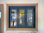
The home was a 1980s single-story contemporary with a long bearing ridge and high vaulted ceilings. A wall approximately 14 feet wide by 18 feet tall supported one end of the ridge and separated the kitchen from a family room at the back of the house. Except for a soffit (which we planned to remove), the only break in this vast expanse of drywall was a 5-foot-wide doorway. Although it wasn’t part of the original plan, the customers told me they were thinking about putting French doors into this opening.
I suggested increasing the size of the opening instead; this would result in a better traffic pattern and give the kitchen a more spacious feeling. It would also let in light from the family-room windows and create a view into the landscaped yard beyond. The owners liked the idea.
The only catch was that the wall carried a large section of roof and was one of the major shear walls in the house.
Need for Shear Walls
Shear walls are designed to resist the forces exerted on buildings by high winds and earthquakes. They resemble regular framed walls but are secured to the foundation with heavy hold-down bolts or straps and are stiffened by a layer of plywood fastened with a specified tight nailing pattern. On the West Coast, shear walls are the main earthquake-resistant component used in residential construction.
We wanted to create a new 9-foot-wide by 8-foot-tall opening in the existing shear wall, which required stamped drawings from an engineer. I faxed elevations of the wall with the existing and proposed door openings to civil engineer Lee McCleary, of Walnut Creek, Calif., who laid out what it would take to open up the wall.
I estimated the cost of the additional work, presented it to the clients, and came away with a signed change order.
Existing conditions. The existing shear wall was framed with 2×6 studs and sheathed on the kitchen side with 3/8-inch plywood nailed 3 inches on-center. It was supported by 2×8 joists and a sill that landed on a concrete stem-wall foundation. In addition to studs and a header, the wall contained three 4×6 posts connected to the foundation with cast-in anchor bolts. Since they would be in the way of the new opening, the posts and anchors had to come out.
According to McCleary, we could take out part of the wall, but only if we replaced the shear value of the area removed.
Shear Panels
With the new, wider passageway, only 30 inches of wall would remain at either side of the opening — far too little to provide the necessary shear value with conventional framing. McCleary’s solution was to replace the end walls with manufactured shear panels, factory-built wall sections that are significantly stronger than site-built shear walls.
Shear panels are frequently used in high-wind and seismic zones to stiffen “weak,” narrow sections of wall, allowing builders to devote more wall area to door and window openings. While shear panels can be installed almost anywhere in a building, the most common location is in the narrow section of wall on either side of a garage door.
Several manufacturers make shear panels, among them Simpson Strong-Tie, Hardy Frames, Shear Transfer Systems, Trus Joist, and R.H. Tamlyn & Sons. The panels are made from wood with a small amount of steel; from steel with a small amount of wood; or entirely from steel. Stock-size shear panels measure anywhere from 12 to 80 inches wide and from 78 to 153 inches tall. For an extra charge, most manufacturers will produce custom heights.
Since tract builders buy panels by the truckload, I assume they get them at a good discount. A small builder should expect to pay $200 to $400 per panel at a lumberyard or supply house.
Design Constraints
In most instances, shear panels are bolted directly to the foundation or slab, but on this remodel we wanted to attach the shear panels to the wood floor to avoid the complication of cutting out and resupporting joists. Although installation is simpler and shear values are higher when you bolt panels directly to a foundation or concrete slab, floor installations are necessary when you’re using panels on the upper levels of multistory buildings.
At first, McCleary considered using Simpson’s Wood Strong-Wall, but when he calculated the load he found that any wood panel wide enough to meet the shear requirement would not fit in the available 30-inch space. And whereas the steel version of this product — the Steel Strong-Wall — was strong enough to work in the available space, it was not yet approved for installation on top of framed floor systems.
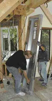
The right panel for the job. Hence, McCleary specified Hardy Frame Panels, steel shear panels strong enough to replace the missing shear value, narrow enough to fit the space, and rated for use over floors framed with wood or light-gauge steel. Steel panels are stronger than similar-sized panels made from wood.
Had the end walls in this house been wider, we could have chosen from a variety of wood shear panels, all of which are rated for use over framed floors.
Preliminary Work
Since we wanted to complete the structural work as soon as possible, we purchased all the materials in advance. Fortunately, they were all stock items: two Hardy Frame Panels, four lengths of 7/8-inch threaded rod, a 6×12 Douglas fir header, a 6×8 Parallam to block joist bays, and multiple tubes of Simpson’s Epoxy-Tie Set adhesive.
As soon as we got permits, we began demolition. We had already removed the soffit and enough drywall to see inside the lower portion of the wall, but we were not certain what was at the top. To be on the safe side, we assumed that the wall carried the roof, and we made plans to shore it up before removing any structural components. First, however, we placed the new header against the side of the shear wall so that the shoring would not interfere with our attempts to maneuver the header into position.
Shoring and demo. I picked a height well above where we needed to cut the studs to insert the new header and removed the drywall and plywood below that line. Then we nailed horizontal 2×6 cleats to both sides of the wall. Next, we wedged long 2×6 supports between the blocks on the floor and the cleats on the wall and nailed them into place. Since the supports came up at an angle, there would be room to work below.
To prevent the supports from bowing, we tied them together with diagonal bracing and ran perpendicular braces to the floor. The shoring did not take long to complete and was quickly approved by McCleary.