Download PDF version (482.2k) Log In or Register to view the full article as a PDF document.

During my 30 years as a carpenter, I have framed several hundred complicated roofs, and have read nearly every book on the subject. A particularly good one is The Steel Square, by H.H. Siegele, which uses drawing techniques rather than advanced math to illustrate complex rafter cuts.

Image

I began using these drawing techniques because I wanted to better understand the geometry of roof planes. Not only did these methods help me grasp the way complex roofs fit together, but they also increased my cutting speed — and have been excellent teaching tools to boot.

In this article, I'll show how I use this technique to develop the basic cuts for an irregular hip. The method explained here is accurate for concealed 2-by roof framing. Where accuracy is more critical — as in the timber-frame homes we build, where a half-degree error on an 8/12 timber valley really shows — I also use basic trigonometry, but that's another story.

Image

Figure 1. When teaching framing to novice carpenters, the author uses a simple cardboard model to help them "think in triangles."

Thinking in Triangles

This method helps you think of a roof in terms of its component triangles and how they relate to each other. All the triangles that make up the roof are drawn on a flat surface. Think of the horizontal leg of each triangle — the run — as a hinge. Once the drawing is complete, the triangles can be mentally rotated on their hinges to form a three-dimensional model of the roof. When I teach this method, I use a cardboard model as a visual aid to show how each part of the roof relates to the others (see Figure 1). Mastering the technique takes time — I'm still learning — but the basics can be grasped quite easily.

Plywood Worksheet

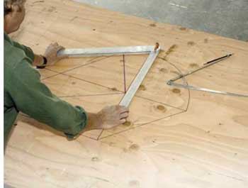
I usually make my drawings on a piece of plywood, using the 12ths scale on the framing square. This makes sense on the job site, and lets me draw the cut angles full-scale. The only special tools I use are a large compass (Lee Valley Tools sells one; 800/267-8735, www.leevalley.com) and an oversized bevel square. The aluminum bevel square in the photos came from Germany, but any large one will work. (Quint Measuring Systems' contractor-grade True Angle Tool is available online in 24-inch and 36-inch lengths; www.quintmeasuring.com.)

The blueprints I'm typically given include only the most basic information about a roof: a plan view, an elevation, and the basic pitches. But this is enough information to develop the drawings, if you follow the correct steps. The easiest method is to break the drawing sequence down into discrete parts, each of which builds on the previous one:

• plan angle for the hip rafter

• common and hip lengths and cut angles

• hip backing angle

• roof surface

Draw the Common and Hip Runs

The example roof has a 5/12 pitch on the hip end and a 10/12 pitch on the building's long dimension, and the eaves meet at a 90-degree angle (Figure 2). Note that I'm ignoring the overhang and working from the plate line.

Image

Figure 2. The full-scale drawing for an irregular hip roof begins with a basic rectangle — a plan view that represents a corner of the roof. The sides are the two common runs; the diagonal is the hip rafter.

To get started, you first have to accurately draw the angle at which the hip rafter intersects the eaves at the corner. I start with an imaginary point on the hip rafter where the rise is 12 inches above the outside of the plate, then determine the run of the common rafters from that point to the plate line. You can do this quickly with a calculator, but I just use a simple table I've printed out (Figure 3).

Image

Image

Figure 3. To start the full-scale layout drawing, the author finds the two common runs at 12 inches of rise; that is, he converts the 5-inch-over-12-inch roof pitch to 12 inches over 28 13/16 inches (left). Rather than do the math each time, he works from a chart.

Image

A 5/12 common rafter has a run of 28 13/16 inches at 12 inches of rise, while the 10/12 rafter runs 14 3/8 inches. I use these numbers to draw a rectangle, which is the basis for all the drawings to follow. A diagonal across the middle (line BD) represents the hip in plan. If you've drawn accurately, you've already got the side cut angles for the jacks, which you can transfer to the stock with a bevel square.

Draw the Common and Hip Rises and Lengths

Next I draw the rise — 12 inches — of one of the common rafters by extending one end of the rectangle (Figure 4). So, for example, I extend line CD 12 inches to point E; this represents the rise of the 5/12 common rafter. Line AE represents the 5/12 common length.

Image

Figure 4. The next step is to "develop" the lengths of the commons (top, center) by drawing right triangles along the sides of the rectangle. The base of each triangle is the common run, the adjacent side is the 12-inch rise, and the hypotenuse is the common length. The hip length (bottom) is developed from the diagonal through the rectangle. Using a compass to swing a 12-inch arc saves time measuring.

Here's where the compass comes in handy. I set its points at D and E, then swing an arc around the end of the rectangle so I don't have to measure the rise three times. Next I draw the 10/12 common in exactly the same way as the 5/12, then the hip, using the framing square to draw its rise (DG) perpendicular to its run (BD).

You've now got the plumb cuts as well as the seat cuts for both commons and the hip.

Draw the Hip Backing Angle

Figuring the backing angles for an irregular hip is usually tricky, but not with this method. Start by drawing a line perpendicular to the hip length, anywhere along its length. Extend the line to the hip run; this is line JK in the drawing (Figure 5).

Image

Image

Image

Image

Figure 5. To develop the hip backing angle (angle LNM in the example), first draw a line perpendicular to the hip length extending to the base of the hip — from point J to point K. Next, draw a line from point K perpendicular to the hip run extending in both directions until it crosses the plate lines (LM). Then, using K as the pivot point, swing an arc from point J to the hip run — to point N in the example. Finally, draw lines from N to L and M; the resulting angle, illustrated in the cardboard model (photo, left), represents the top of the hip rafter.

Next, starting at point K, draw a line perpendicular to the hip run and extend it far enough in both directions that it crosses the plate lines (LM). You may have to extend one or both of the plate lines, as in the drawing, in order to intersect this new line.

Now I set the point of the compass on K and swing an arc from J to the hip run; the intersection is point N.

Finally, drawing lines from this point — N — to points L and M gives you the backing angle for the hip rafter.

Draw the Roof Surface

You can also easily figure out the angled cuts for the roof sheathing (Figure). Put the point of your compass at point A and the pencil end at E — the distance along the 5/12 common length. Then swing this arc in the opposite direction, make a mark, and extend the 5/12 run line (AD) until it intersects at point O. Draw a line from O to B; the triangle you've drawn represents the roof surface on the 5/12 side of the hip rafter.

Repeat these steps for the other side (triangle BCP).

Image

Image

Image

Figure 6. To draw the sheathing cuts at the hip corner, first extend both common runs well beyond the plate lines, then draw arcs from the tops of the common lengths to these new line extensions (arcs EO and FP). The cardboard model (left) shows how rotating triangle OAB creates a perfectly fitted roof surface.

Image
Image

Image
Image

Figure 7. Pulling cut angles off the developed drawing is a matter of setting the bevel square and transferring the angles to the stock. Here, the author transfers the plumb cut for the 10/12 common (A, B) and sets the bevel angle for the 5/12 hip backing (C, D).

At this point, you can transfer the cut angles to the stock for cutting (Figure 7).

William Dillon is a job supervisor with South Mountain Co., an employee-owned design-build firm on Martha's Vineyard, Mass.