Normally, replacing an old stamped concrete patio with a low-level composite deck on essentially the same footprint is straightforward. On the project shown here, however, there were a number of complicating factors—the main one being that the house was clad with brick-veneer siding, which meant that we couldn’t fasten a conventional ledger to it.
Brick-veneer homes are fairly common in our part of Michigan, and our standard approach with such homes is to simply build a freestanding deck. But in this case, the homeowners wanted the decking to wrap around a cantilevered bay and an existing chimney that were within the new deck’s footprint. More importantly, they wanted to be able to step through the bay’s sliding door directly onto the deck. And, because the deck framing was so low to the ground, we couldn’t install a dropped beam close to the house and cantilever the framing back to the house.
This wasn’t the first time we had encountered a situation like this, and we’ve developed an approach that allows us to safely fasten decks to these types of homes without a cantilever. Here’s how we did it.
Flush Beam Provides Better Clearance
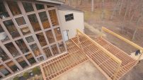
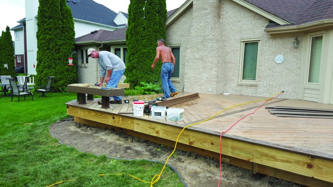
Our clients’ concrete patio had cracked and shifted, which is why they wanted to replace it with a deck. Getting rid of the old concrete posed a problem because the lot was narrow, and the equipment needed to break up and remove the concrete was too big to be maneuvered into the backyard. Since the new deck would completely cover the old patio, we decided to leave it in place and build over it.
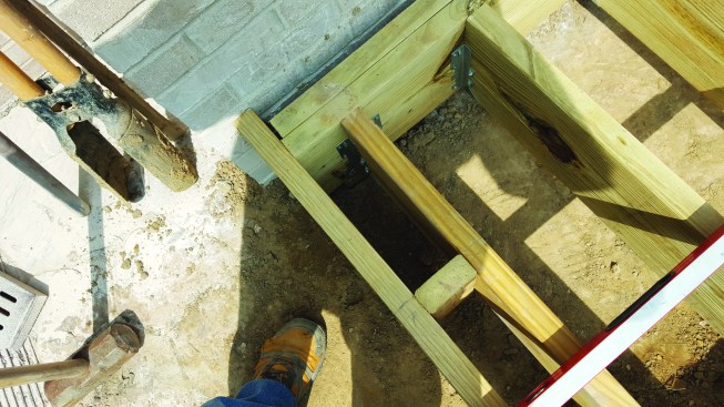
The new deck was built over an old concrete patio. At the bottom of the photo, you can see one of the holes that were cut through the slab in order for us to dig down below frost level and install a proper footing.
The next challenge was the footings. The deck is a bit larger than the patio, so the footings for the posts that would support the rim beam could be located outside the patio’s perimeter. To install the footings for the four posts that would support the beam closest to the house, however, we had to use our gas-powered concrete saw to cut 2-foot-by-2-foot squares out of the patio.
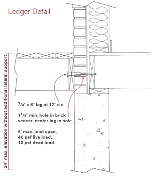
Oversized holes through the brick veneer are required in this ledger connection detail to prevent loads from being placed on the cladding. Joists must be shorter than 6 feet, and lateral load anchors are also required when the deck is taller than 2 feet above grade.
With a freestanding deck, the inside post-and-beam assembly would need to be located a couple of feet from the house to allow for the joists to be cantilevered over the dropped beam and back toward the house. On this home, which has a full basement, that would put the posts within the 5-foot backfill zone. Because footings must bear on undisturbed soil, we would have needed to place the post footings at about the same depth as the bottom of the basement footing, or about 8 or 9 feet deep. Instead, we located the footings about 5 1/2 feet away from the house and had to dig only down to frost depth, which is 42 inches in our area.
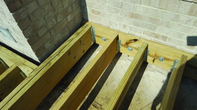
Obviously, we couldn’t cantilever the deck joists 5 1/2 feet past the support beam; and even if that were possible, there wouldn’t have been enough clearance below the deck joists for us to install a dropped double 2×10 beam. We like to provide ground-level decks with plenty of cross ventilation so air movement beneath the deck can dry out the underside of the decking and framing. And there should also be enough clearance that there is no contact between the ground and the framing. Our only choice was to install a flush beam and support the joists with joist hangers.
Low-Load Ledger
This solution works, of course, only if the joists can be hung from a ledger attached to the house. So we contacted our engineer, who confirmed that a ledger-connection detail through brick veneer that he had designed for us in the past would work on this project as well.
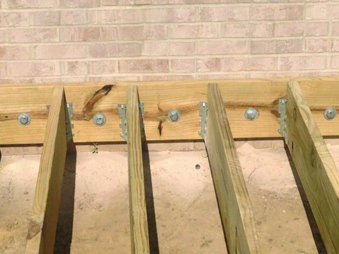
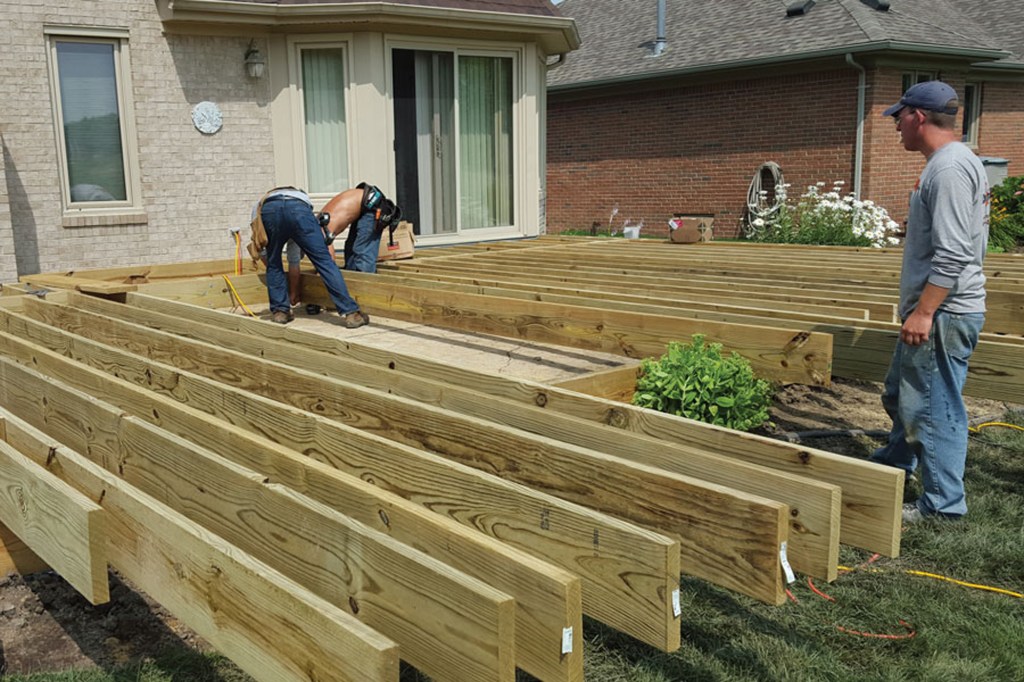
The ledger was fastened to the house rim joist with 3/4-inch-by-8-inch galvanized lag screws installed on 12-inch centers.
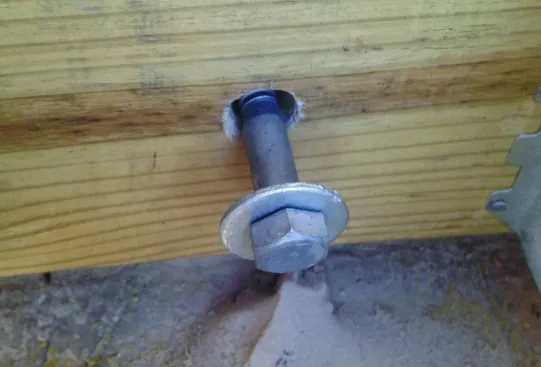
Structural deck ledger screws (left) are easier to install than 1/2-in. diameter galvanized lag screws (above), because pre-drilled holes aren't required. But they must be installed following the manufacturer's specifications, rather than according to prescriptive guidelines in the IRC.
To limit loads that the ledger must be able to support, joist spans must be limited to less than 6 feet when this detail is used. In addition, it’s important to avoid putting any loads on the brick itself. To do that, we drill oversized 1 1/2-inch-diameter holes through the brick for the 3/4-inch-diameter by 8-inch lag bolts that we use to fasten the ledger to the framing. This way, the lag bolts don’t actually bear on the brick, minimizing the risk of cracking the brick from the deck loads. We install the galvanized lag bolts every 12 inches on-center into the house rim joist to support the short spanned ledger.
We’ve successfully used this detail on a number of projects similar to this one— always with the preliminary approval of our inspector. If the deck were more than 2 feet above grade, we would have needed to install additional lateral load anchors.
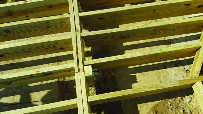
The ledger couldn’t be attached to the masonry chimney, which requires a 1-inch-minimum gap between the brick and the framing.
To support the framing at the corner of the deck near the chimney, the author had to install a post, which extends about 9 feet below grade and bears on the chimney footing
This connection detail allowed us to provide a ledger attachment everywhere except where the chimney is located. Codes require a 1-inch gap between deck framing and a masonry fireplace chimney, so we needed to install a deep, 4×6-inch support post at one corner in order to help support the beam around the chimney.
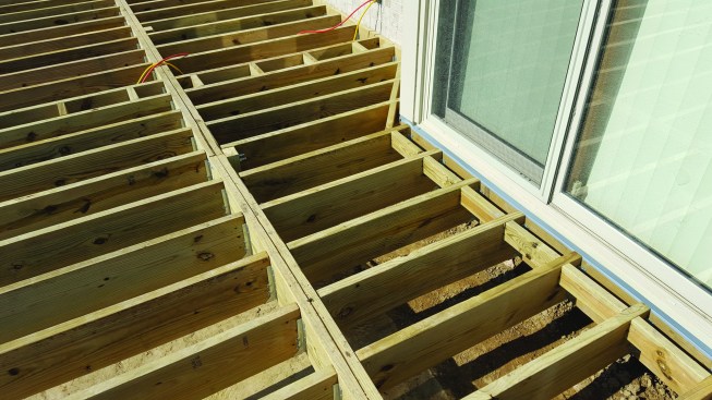
Siding and trim had to be removed from the cantilevered bay before this section of the ledger was installed. Deck loads here are supported primarily by the flush beam, with the cantilever ledger serving mainly for lateral attachment. Note the blocking, which eliminates the need to fasten the decking to the ledger through the L-flashing.
Cantilevered Bay
The deck ledger that we attached to the cantilevered bay carries minimal loading. In fact, its primary purpose is for lateral support. Still, it must be properly f lashed, which means we needed to remove some of the siding and trim before fastening the ledger. I cannot count how many times I have seen unflashed deck ledgers installed directly over house siding, which allows water and debris to collect and promote decay and rot. Here, we installed preformed plastic ledger flashing that runs about 3 inches up behind the siding and extends out over the ledger.
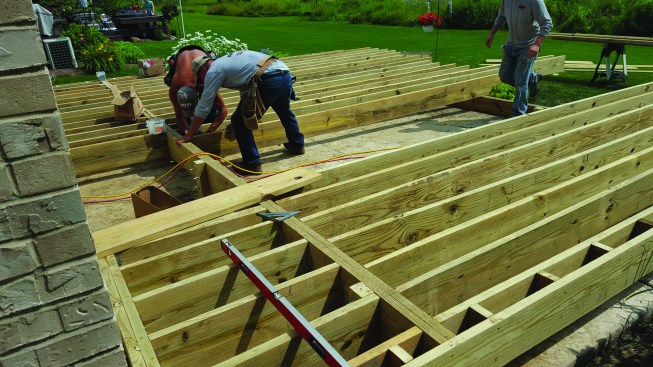
Because the composite decking would be installed at a 45-degree angle to the framing, the joists were installed on 12-inch centers to meet the decking’s span requirements.
Blocking installed around the perimeter of the frame (left) supports the picture-frame detail used to finish the decking
Because we planned to install the decking at a 45-degree angle to the framing, we had to adjust the joist spacing to match the decking’s span rating. In this case, we installed the joists 12 inches on-center to meet the requirements of the TimberTech Legacy decking we used.
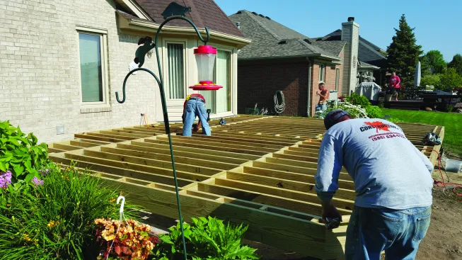
A contrasting seam board in the middle of the deck highlights the diagonal decking.
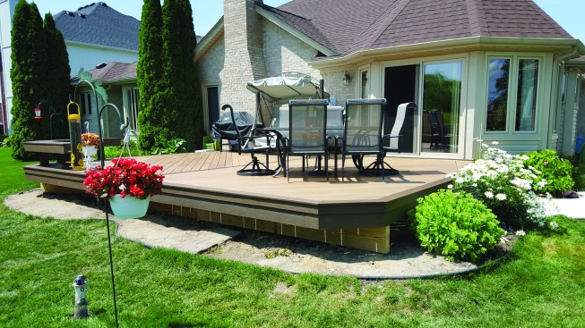
The deck has a tiered fascia detail, which makes the edge of the deck appear narrower.
We usually picture-frame our decks, not only because it looks good but also because it provides better protection for the tiered-fascia cladding we like to use (see “Upgrade to a Tiered Fascia,” March 2013). On this project, we also installed a contrasting center seam board, to add visual interest. For details like these, we always install vertical blocking, which drains better than blocking installed on the flat.
Photos by Bayn Wood