The International Residential Code, the American Wood Council’s DCA-6 Prescriptive Residential Wood Deck Construction Guide, and other standard industry publications all do not permit or recommend the attachment of a deck ledger to any cantilevered floor system, be it solid-sawn, I-joist, or floor trusses. But we still see examples of just this practice, sometimes following guidance from I-joist and floor-truss manufacturers. In this article, we will explain some of the technical obstacles facing a homeowner and deck contractor when considering the addition of a deck to a new or existing home with a floor system built with open-web floor trusses, with a particular focus on the structural problems that arise when attempting to fasten a deck ledger to cantilevered trusses.
Background
To ensure that decks are positively anchored to the primary structure for vertical loads, the IRC spells out how these loads are to be transferred to the primary structure by use of a band board, or rim joist. Section R507.9.1.2 in the 2021 IRC clarifies the point by stating that the band joist shall bear fully on the primary structure, as in providing wood-to-wood bearing, capable of supporting all the required loads.
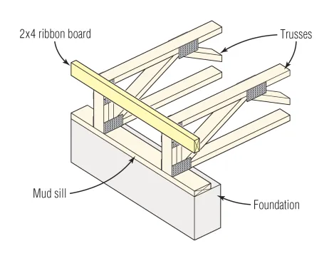
In a typical floor system framed with truss joists, a nonstructural ribbon board is attached to the top of the floor trusses, as shown here. This 2×4 ribbon board is not intended for a deck ledger attachment.
However, when floor trusses are installed, a band joist is not present; instead, a nonstructural ribbon board is typically attached to the top of the floor trusses (see drawing, left). This presents a problem for deck builders because the 2×4 ribbon board is not structurally adequate for a deck ledger attachment. Both the Structural Building Components Association and the AWC (in DCA-6, Figure 13B) specifically indicate that the 2×4 ribbon board is not intended for deck attachment.
Cantilevered Trusses
The SBCA’s research report SRR-1408-01, “Attachment of Residential Deck Ledger to Metal Plate Connected Wood Truss Systems,” provides solutions for deck ledger connections to floor trusses (see editor’s sidebar, “Truss Industry Ledger Details”). The fastener schedules in SRR-1408-01 are based on the essential assumption that the floor trusses are supported by “wood-to-wood bearing” at the location of the deck ledger attachment. SRR-1408-01 does not provide recommendations for cantilevers.
Of course, one pathway for a homebuilder to accomplish a safe deck ledger connection to a cantilevered floor system is to pursue an engineered solution based on the IRC’s “Alternative materials, design, and methods of construction” provisions. Recently, we explored options for connecting a deck ledger to cantilevered floor trusses by reviewing related wood truss design resources, and proprietary fastener and connector literature.
Structural considerations. In a typical cantilever truss detail, 2×4 ribbon boards are nailed across the ends of the trusses at the top and bottom, with short verticals called “ribbon blocks” sometimes attached to the ends of the trusses and ribbon boards with 1×3 or 1 1/2×3 plates (see floor truss cantilever illustrations, below). To help visualize a plated cantilever floor truss, we referred to a detail published by Mitek in 2011 that shows the cantilever supporting a load-bearing wall. Note, however, that the detail does not indicate the vertical 2×4 ribbon block is a suitable connection point for supporting a deck ledger.
Click to enlarge image below

Tim Healey
Above at left is a problematic bolted deck-ledger-to-floor-truss connection. Note that the bolts anchoring the proposed deck ledger to the floor system must span a 3 1/2-inch-wide gap between the blocking spanning the truss ends and the inside face of the wall sheathing, a precarious and improper connection detail with unknown capacity to support occupant live loads. Above right is a cantilevered truss designed to support a load-bearing wall but not a deck ledger. The vertical 2×4 ribbon block is not a suitable connection point, with the vertical load capacity limited by the strength of a structural connection between the deck ledger, sheathing, ribbon block, and plated end vertical. Engineering is always required for a proper structural connection between a deck ledger and truss floor system.
Assuming a deck contractor attached a deck ledger to 2×4 ribbon blocks, the vertical load capacity of the deck ledger connection would be limited by the strength of a structural connection composed of four elements—deck ledger, sheathing, ribbon block, and plated end vertical. Connecting a deck and ledger to this detail creates a unique design challenge. When a deck ledger is spaced 2 inches from a truss end vertical that is connected to both the top and bottom chords, what are the allowable design values for 1/2-inch bolts, 1/2‑inch lag screws, or 1/4-inch structural screws?
Mind the gap. Fastener schedules and spacing requirements for connecting deck ledgers to fully supported solid-sawn band joists have been available in the IRC since Table R502.2.2.1 was included in the 2009 version. The tabulated values were based on laboratory load tests of deck ledger–band joist connections made with a 1/2-inch-diameter bolt or 1/2-inch-by-4-inch lag screws (see “Load-Tested Deck Ledger Connections,” Mar/04). In this study, researchers tested only two simulated connection configurations for the space between a deck ledger and house band that was fully supported on steel. In one, the space between the ledger and house band was occupied by a piece of 15/32-inch OSB and it did not bear on the steel test bed. For the other case, the space between the ledger and house band was occupied by a 1/2-inch-thick stack of washers and 15/32-inch OSB. These details matter, as testing showed that the amount of space between connected members impacts both the strength and deflection behavior of the assembly.
For connection analysis purposes, the short vertical, or “ribbon block,” and wood sheathing would act as a spacer in the connection of a deck ledger to the top chord and bottom chord metal-plated end vertical. As this would be the critical link in the load path to wood-to-wood bearing on a wall and ultimately to the foundation, we reviewed the 2021 IRC Table R507.9.1.3 (1) “Deck Ledger Connection to Band Joist” under the 40-psf-live-load column to determine if the tabulated maximum spacing of bolts or lag screws would apply to connecting a deck ledger to the end verticals of the trusses through the 2×4 ribbon blocks. This table contains values only for connections that are separated by no more than 1/2 inch or 1 inch, while the members are spaced 2 inches apart in the ledger connection detail described above, and, therefore, the tabulated data do not apply. We are not aware of published test data for a 1/2-inch-diameter bolt or lag-screw connection between a horizontal member (ledger) and 2×4 member (end vertical) separated by 2 inches.
High-strength 1/4-inch-diameter structural screws that have been tested and rated for a 2-inch spacer between the ledger and plated truss end vertical could be a design option to transfer ledger loads to the plated end verticals. For the ledger connection depicted in “Floor Truss Cantilever,” above right, the minimum screw size would be 1/4-inch diameter by 5 inches. Simpson Strong-Tie publishes lateral design values for a deck ledger connection that has solid bearing on a wall and the space between members is limited to 1/2 inch, not the 3 1/2-inch space for the connection shown in “Unsafe Ledger to Truss Connection,” above left, or for a cantilever truss detail, as shown on the right.
FastenMaster also publishes lateral design values for its LedgerLok 1/4-inch-diameter structural screws, limiting the spacing members to 1 inch. Again, we are not aware of any manufacturers of 1/4-inch-diameter high-strength screws that have published lateral (shear) design values for deck ledger applications wherein the members are separated by 2 inches.
Recommendations. Absent published fastener design values for a “deck ledger to sheathing to ribbon block to end vertical” connection, our recommendation is that builders and deck contractors should not pursue an engineered ledger connection for a truss cantilever with ribbon block. Alternatively, a fastener or connector manufacturer may be able to develop a tested ledger-to-truss-cantilever connection system with installation instructions for use by builders, deck contractors, and building code officials.
In addition, since the cantilevered-truss-to-ledger connection deflects in service based on deck, floor, wall loads, and potentially roof loads, special consideration would need to be given to water or moisture details that will accommodate the likely cantilever deflection and rotation of the truss end vertical.
Since the integrity of the deck ledger connection is a life-safety issue, we recommend that any requisite engineering design work for consideration by the jurisdiction (under IRC R301.1.3) include:
- Specification of the proper deck-related live, dead, and lateral loads to the end vertical of the cantilevered trusses.
- Connection designs.
- Flashing design details.
- Copies of truss design drawings of the affected trusses for documentation by the jurisdiction, homebuilder, and homeowner.
At least for floor-truss cantilevers, coordination between the professional engineer and the truss manufacturer would be critically important. Differences in truss details are subtle, and some truss end details will better accommodate an engineered deck ledger connection than others.