In a previous article, we described how our design-build company completed a job using helical piers to support a replacement foundation in unstable soils (“A Pier-and-Beam Foundation for a Coastal Site,” 7/08). Early last year, we were called on to stabilize a late-1970s home that was gradually slipping down its sandy 30-degree slope. Despite its precarious state, the owners were still living there, but they were ordered to vacate by the local building commissioner before he issued the permit to repair.
Truly Original Conditions
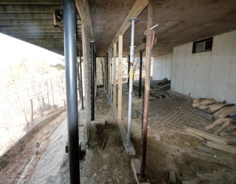
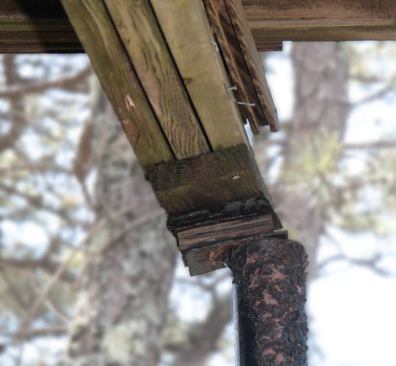
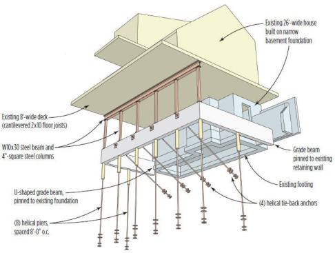
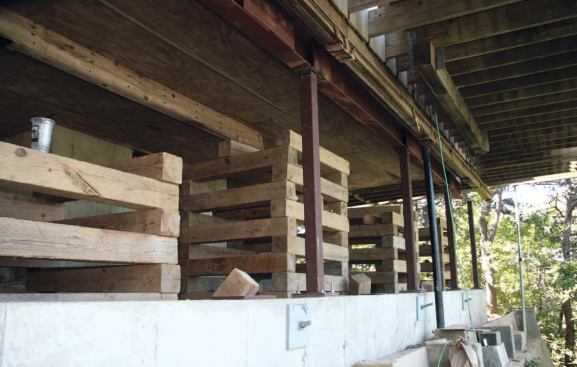
The 26-foot-wide house was built on a narrow basement foundation that had been cut into the slope. The original concrete foundation carried only 10 feet of the total span The rest of the structure was supported on freestanding 4-inch round steel columns on 8-foot centers. These stood on a concrete grade beam, which had been formed on top of fill removed during the foundation excavation and simply pushed downhill. Obviously anticipating a tendency for this stuff to slide, the builder had cast heavy steel chain into the grade beam and tied it back to the basement footing.
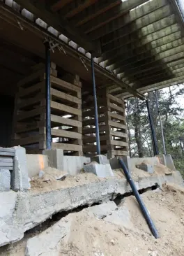
Slip-sliding away. Thanks to washouts that had occurred over the years beneath the grade beam, we could see the tops of tube-formed concrete columns, which had evidently been placed there to support the beam but were now tilting radically downhill. Although we didn’t do any exploratory excavation, it was clear that these columns did not extend very deeply – if at all – into the undisturbed original grade.
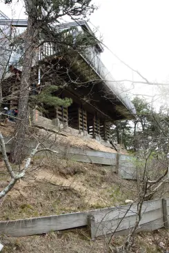
Apparently the fill, as it gradually redistributed downhill, was pulling the columns along with it, so that the beam was settling down and away from the structure it was meant to support. A pressure-treated-wood retaining wall further down the slope was literally bursting at the seams, doing nothing to arrest the downhill progress. When we began work, the “flying” section of this two-story house had dropped nearly 3 inches out of level. To make things even more interesting, a deck built on cantilevered 2×10 floor joists extended another 8 feet out over the abyss. It was a hair-raising place to stand.
Helical Piers to the Rescue
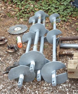
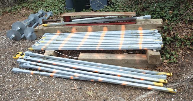
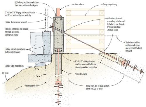
Had the grade beam been installed over pilings that penetrated more deeply into stable hillside – well beyond the incident angle – the installation might not have failed. Our proposal, based on our experience working with helical piers, would correct that error. The plan was to drive vertical piers deep into the hillside to support a new grade beam formed directly behind the old one. Helical tie-back anchors driven into the slope would resist the lateral forces from the uphill side of the grade beam, enabling it to do double duty as a support and a retaining wall (see illustration). Since removing the old grade beam would be highly impractical and expensive, we’d just leave it in place.
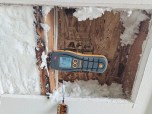
We hired an engineering firm to provide the design parameters and certify the actual pier insertion. To ensure predictable performance, each helical pier must be driven to both a specified depth and a particular value of resistance to insertion. The concept is simple: Cumulative soil pressure on the piers’ helical plates provides the necessary support, measured in kips (kilopounds, or 1,000 pounds of force), to meet the design load. In the case of the tie-back anchors, the soil pressure also resists pullout.
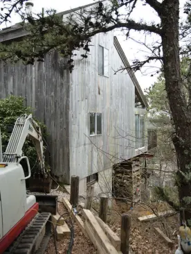
Tight Access
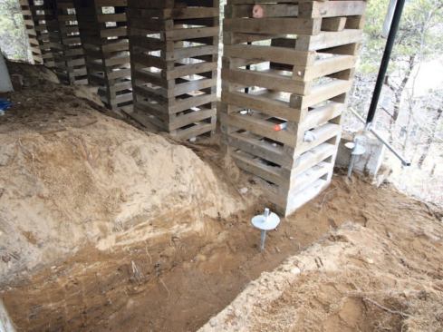
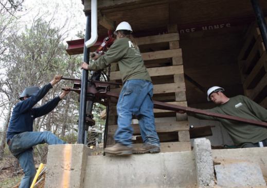
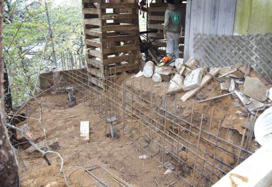
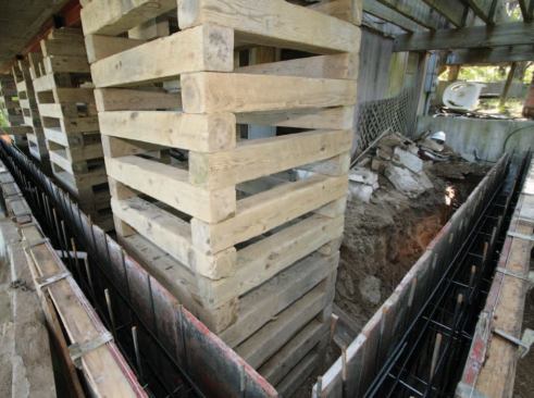
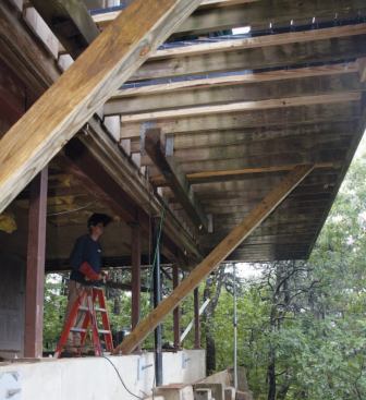
This site didn’t allow access for any kind of heavy machinery, so in order to temporarily support the building on cribbing, we hand-shoveled a level base between the foundation and the old grade beam (Figure 3). To make sure we didn’t impose any more lateral pressure at the top of the failed grade beam, we dug down to its base. Then, leaving just enough space in which to form the new grade beam, we set up five stacks of cribbing beneath the full length of the building. Next we brought in a steel I-beam in sections short enough for four guys to lift by hand. We set the steel on top of the cribbing and welded the sections together to form one continuous lifting member. Now we could jack the building – just far enough (for the time being) to take the pressure off the failed supports. Hydraulic jacks were set inside each cribbing stack under the beam and raised simultaneously via a central manifold. To provide the hydraulic power, we ran lines from the takeoff on our mini-excavator, which was parked at the top of the hill.
To set up jacking stations and restore the building to a level c…
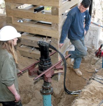
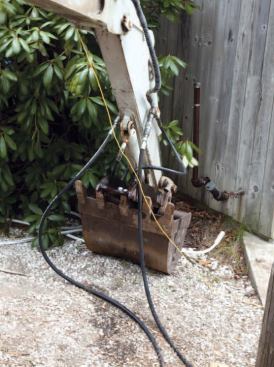
Positioning the Auger Head
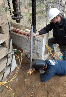
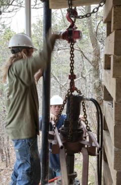
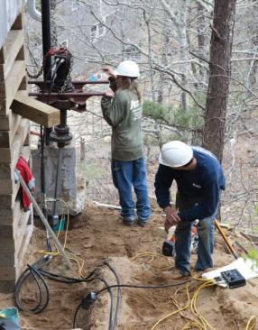
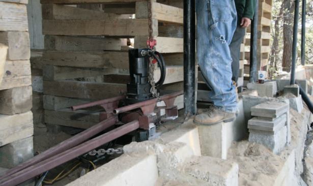
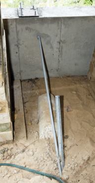
Helical piers are driven into the ground using a hydraulic auger head. Driving a pier to specified depth takes several thousand foot-pounds of torque. On a more-or-less level job site, we’d mount the auger head on the mini-excavator’s boom; the 8,500-pound excavator itself provides enough dead weight to resist the considerable reverse torque generated during pier insertion. However, since we couldn’t place the excavator in the work zone, we fabricated a hand-portable welded steel frame to hold the head, incorporating a drag bar that we could jam against any adjacent immovable object (Figure 4). We supported the head over the insertion site with an overhead chain lift suspended from a beam inserted in the cribbing. This worked well for the vertical piers. In most cases, the old grade beam provided an immovable stop for the drag bar. At one point, a nearby tree trunk came in handy. We installed all eight piers called for within two days. For certification purposes, we monitored the progressive hydraulic force required to install each pier with a digital console, and recorded the readings in a log.
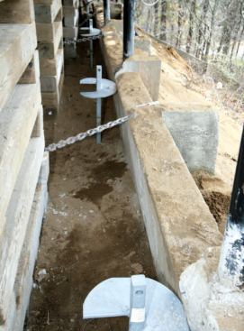
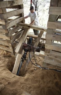
Installing the four tie-back anchors was more of a challenge (Figure 5). The tie-backs were located in the spaces between the cribbing stacks. These spaces were too tight for us to extend the drag bar, and we struggled for a while to find an alternative bracing method. The counter-rotational force tended to push individual cribbing members out of position, threatening to topple the stack. After some trial-and-error modifications, we got the cribbing to resist as an integral unit. These four anchors took another two days to install.
Heavy steel bearing plates welded to the tops of the piers suppo…
Reinforcing Steel
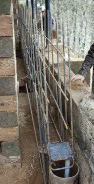
With all the piers finally installed, we turned to fabricating the rebar cage for the 12-inch-wide grade beam (Figure 6). This called for a hefty schedule of #4 bar, 12 inches on-center vertically at both wall faces and tied to continuous horizontal bar along the top and bottom of the beam. We returned both ends of the grade beam to the basement foundation, using epoxy grout to tie the rebar in.
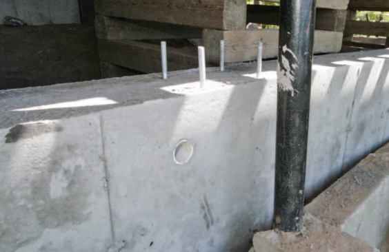
To tie the grade beam to the helical piers, we welded 8-inch by 8-inch by 3„4-inch-thick galvanized steel cap plates to the end of each pier, then welded the rebar cage to the caps. At the tie-back locations, the grade beam is tied to the anchors with threaded shaft extensions, which are secured with nuts and heavy steel spread plates on the beam’s outer face ( Figure 7). Before placing the concrete, we aligned 4-inch-diameter PVC sleeves inside the forms at the approximate anchor shaft angle; this gave us some play on the angles when connecting the extensions.
Setting the Steel I-Beam
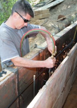
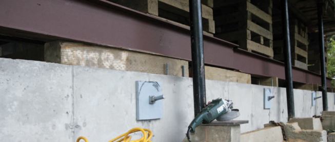
We pumped 4,000-psi concrete into the forms and let it set up over the weekend. The following week, after stripping the forms, we brought in two 20-foot lengths of W10x30 steel beam, which would permanently support the building. We laid them end-to-end on wood blocks on top of the grade beam, trued them to a laser line, and welded them together to form one continuous beam (Figure 8).
The I-beam is supported on 4-inch-square structural steel columns. We centered their base plates along the top of the grade beam, 8 feet apart, and leveled them over fast-setting hydraulic cement. Four bolts epoxied into the top of the grade beam hold each base plate in place. We cut the posts to rough length, then plumbed them and welded them to the base plates.
At this point we jacked the building up to its final position, close to but not perfectly level. Structural sag slowly instilled over three decades can’t be abruptly reversed without risk of damage. We brought the building back to within 1„2 inch of level, leaving only a few cracks in the drywall to patch.
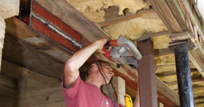
Now we could make a precise allowance for the beam dimension and cut the columns to exact finish length. A hand-held band saw made short work of these cuts. We jacked the beam up, slid it over onto the columns, then welded it in place. The top flange is bolted to the floor framing, tying the structure together. We also welded stiffeners on both sides of the web at each column location to help transfer the overhead load. Finally, to take the scary bounce out of the cantilevered deck, we installed 4×6 pressure-treated diagonal braces up from the top of the grade beam.
Cost
It costs more to build on steep lots like this one, so they tend to sell for less than adjacent, more accessible parcels. At the time of original construction, with easy machine access and no building dangling dangerously overhead, the work we did would have been a matter of a few days and far less money. As it turned out, the job ran about six weeks and cost $50,000.
Fred Ambrose owns Ambrose Homes in Wellfleet, Mass. Ezra Ambrose, his son, manages the job site.