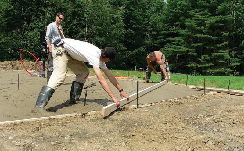
Site Layout for Structural Slabs
Site Layout for Slab Foundations
When framing a floor system, there is a little latitude in both the timing and installation of the utilities. But when building on a slab, the utilities must be defined precisely before any concrete is poured.
Plumbers First
When starting layout, make sure the plumber is the first trade on site. Let other subs work around him — it’s a lot -easier for an electrician to work around obstructions than it is for the plumber.
Before excavation begins, work through the plumbing plans to define all drain/waste and supply lines and vent stack locations, and review plans for all utilities running below the slab, such as electric, gas, and phone lines.
Subslab Utilities
After the service lines have been installed, all plastic or copper lines should be properly bedded (clean fill, no rocks) and tested for leaks prior to backfilling. All copper should be checked for dents or abrasions and wrapped in split-foam insulation, or something similar, to protect it.
Install caution tape: Make sure every trade buries color-coded caution tape 12 in. below grade and in line with their work (Figure A). These plastic caution tapes are color coded: red for electric, blue for water, green for sewer, yellow for gas, and orange for phone.
Mark location of new work: Use spray paint to color-code the location of new work after backfilling trenches. It’s easy to forget where lines run a few days after a trench has been backfilled. Don’t leave anything to memory: Before the concrete trucks show up, make notes either on the drawings or in a site log.
Slab Layout Checklist
Keep careful track of these critical layout details for structural slabs:
Benchmark: A slab excavation should be as level as possible. Set an elevation benchmark prior to excavation. Place the benchmark somewhere convenient and make sure everybody on the site knows where it is (Figure B).
Concrete formwork: Form monolithic slabs as shown in Figure C. Double-check forms, verifying that they are located properly, both in relation to the corner points the surveyor set prior to excavation and in relation to the elevation benchmark.
Reference lines: Mark on the edge of forms one reference point from which each subtrade can take dimensions and work. A string line across the forms is ideal. Locate this reference line at some feature of the building that cannot change, such as the longest bearing wall. Make sure that all trades clearly understand how this line corresponds to their work.
Edge of slab/wall: Take time to understand the -relationship between the edge of the form and the edge of the wall. Explain it to the plumber and other subs (Figure D).
Penetrations: Double-check all penetrations before the slab is poured. These include toilet flanges, drain boxes, turn-ups for water, electric, gas, phone, and floor drains.
Subgrade and Subbase
Subgrade material should consist of well-drained native soil. If soils are not suitable, excavate and replace with a deep subbase layer of compacted gravel.
Granular fill, such as gravel or a mixture of sand and -gravel, works best as a subbase under a slab because it compacts well (Figure C). The fill should be completely thawed and free of organic material — melted ice and decomposed organic material will leave voids (see Soils).
Base Compaction
Residential slabs, even with steel reinforcement, cannot span over voids or soft spots (the amount of steel used is not enough for structural reinforcement unless designed for that purpose by an engineer). Compact subgrade and -subbase after utility trenching to prevent settlement, and under footings to provide even bearing strength.
Compaction is usually expressed as a percentage at -optimal moisture content — usually 95% or greater (see Compacting Soil). Run a plate tamper or- jumping jack until there is very little impression left with each successive pass.
All fill material should be reasonably free of moisture, but if it’s too dry, you can pound on it all day and it won’t compact much. In this case, spray it sparingly with water.
Level Base
The subbase must be graded to the same level across the full width of the slab. Level the subbase to within 1/2 in. (less than 12.4% of a 4-in. slab). Where subgrade elevation is inconsistent, the slab will vary in thickness. This variation will cause it to cure unevenly, which will stress the concrete, increasing the likelihood of cracking.
Subslab Vapor Barriers
Install a subslab vapor barrier on interior slabs to keep moisture and soil gases from entering the home. Use a minimum 4-mil to 6-mil poly. For best results, use a cross-woven poly. Lap seams by at least 6 in.
Capillary Break
An optional 3- to 4-in. layer of sand or gravel over the poly, directly under the slab, helps reduce concrete curling and cracking by allowing water to escape from the slab at the bottom as well as the top (Figure E). Damp sand is typical, but gravel or a sand-gravel mix can also be used.
Concrete For Structural Slabs
Depending on the slab’s purpose, use a 3,000-psi to 4,000-psi mix (Figure F) at a 4-in. slump (for increased workability, consider a water-reducing admixture). For a harder surface, use a 6-bag mix. For more information on concrete mixes, see Concrete.
Use air-entrained concrete for slabs exposed to freezing.
Figure F: Concrete for Slabs
| Floor Class | Application | Minimum Thickness | 28-day Strength | Slump |
|---|---|---|---|---|
| 1 | Residential or tile covered | 4″ | 3,000 psi | 4″ |
| 2 | Offices, churches, hospitals, schools, ornamental residential | 4″ | 3,500 psi | 4″ |
| 3 | Drives, sidewalks for residences, garage floors | 4″ | 3,500 psi | 4″ |
| 4 | Business or commercial walks | 5″ | 3,500 psi | 4″ |
| 5 | Light industrial and commercial | 5″ | 4,000 psi | 3″ |
Bearing on Slabs
Increase the thickness of a slab to 8 in. under bearing walls and structural columns (Figure G).
In thickened bearing pads and exterior wall footings, lay two #4 rebars (see Rebar).
Under a fireplace, thicken the slab to 12 in. and use #5 rein-forcing bars, placed 12 in. o.c. each way to form a grid-work.
Steel Reinforcing for Slabs
To limit cracking, residential slabs require steel reinforcement — either rebar or welded wire. This steel does not increase the load-carrying strength unless purposely engineered to do so.
Rebar
In the field of a slab, use #3 or #4 rebar at 16 in. o.c. Place rebar in the center of the slab section. Use dobies or wire chairs to hold the steel off the ground. Do not use brick to support rebar, because it will pull moisture out of the surrounding concrete too quickly, creating a stress point.
Pipe or conduit laid directly on the ground will dramatic-ally weaken the slab by effectively creating a score line on the bottom (tension) surface.
Welded-Wire Mesh
To effectively limit cracks, 6×6 wire mesh in slabs should be placed in the upper part of the slab, where cracks are noticeable, but no closer than 2 in. to the top surface. Use dobies or wire chairs to hold the steel off the ground.
At slab edges, curve the mesh down into the perimeter footings (Figure: Forming a Structural Slab in Site Layout for Structural Slabs). Do not lap wire sections at joints. Instead, stop the mesh several inches back from the joint location.
If control joints are spaced close together, and a low-slump mix is used, wire mesh is probably not necessary.
Control Joints for Slabs
Three kinds of joints are used in concrete slabs (Figure H):
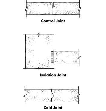
Control joints (center) extend only partially into the slab surface and determine where cracks will form. Isolation, or expansion, joints (top) extend all the way through the slab and allow sections to slide back and forth without cracking. Cold joints (bottom) are necessary when a pour must be interrupted, and should coincide with control joints.
- Control joints confine cracks to intended locations
- Isolation joints allow structural and non-structural elements to move separately
- Cold, or construction, joints define where a concrete pour has been interrupted
Cutting Control Joints
Control joints can be tooled in the slab surface with a grooving trowel or cut with an abrasive or diamond circular-saw blade at recommended spacing and depths (Figure I). Make tooled joints during finishing, as soon as bleed water has evaporated. Cut sawn joints as soon as possible after finishing the slab. Random cracks may appear as rapidly as within six hours in hot weather.
Figure I: Control Joints for Slabs
| Slab Thickness (in.) | Joint Spacing (ft.) | Joint Depth (in.) |
|---|---|---|
| 4 | 8-12 | 3/4 to 1 |
| 5 | 10-15 | 1 to 1 1/4 |
| 6 | 12-18 | 1 1/4 to 1 1/2 |
| 7 | 14-21 | 1 3/8 to 1 3/4 |
| 8 | 16-24 | 1 5/8 to 2 |
| 9 | 18-27 | 1 3/4 to 2 1/4 |
Isolation Joints
Provide isolation, or expansion, joints at garage and basement slab edges (Figure J) and at column footings (Figure K). This prevents movement of one element from damaging the other. Expansion joints can be made of asphalt-impregnated fiberboard or a plastic strip that can be zipped off after concrete is placed.
For a finished appearance in slabs, score fiberboard expansion material prior to placing, so it can be snapped out and the joint sealed with caulk (Figure L). This same detail should be employed with exterior driveway expansion joints; in this case, the caulk provides an important protection from potential freeze-thaw damage (see Concrete Drives).
Basement slabs must also be isolated from the footing, either with sand (Figure: Parging for Concrete Block Foundation in Dampproofing) or with 15# felt (Figure J).


