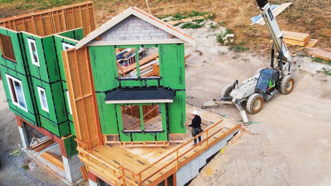
We recently framed a three-story house with a gable on the tall side, our third time building this particular design. The first two times, we used conventional platform framing because the ground was too wet with too much slope to safely use a forklift to lift the walls in place. But on this project, the site was firm and dry, with plenty of maneuvering room, and because we were down to a two-man crew, we wanted to balloon frame the walls to keep the project moving along. In this article, I’ll explain in more detail how we balloon frame walls and what some of the benefits and drawbacks of this approach are.
Basically, balloon framing means using long studs to frame continuously from the bottom plates of the first floor to the top plates of the top floor. This is oversimplified, of course, but in general, we typically try to balloon frame the tall walls in great rooms, entries, and stairwells. Contrast this with platform framing, in which walls that stop at ceiling height are framed on top of each floor.
Balloon framing is not new; in fact, many homes built in North America before the 1950s were balloon framed. Because they typically were framed without blocking for fire separation between the walls and the floors, these homes are at greater risk from fire. [Editor: “fire stops” were addressed in the model Uniform Building Code (UBC) when it was first published in 1927, but adoption of that code was sporadic at first and limited to mostly western states.] As I’ll explain in more detail below, fire blocking is an essential part of our modern balloon framing process.
Why Balloon Frame?
One of the fundamental principles that guide our jobsite decision-making is safety; specifically, limiting the need to work at height. This can’t always be avoided, but whenever we work with tall walls and gables, we try to balloon frame them as a way to reduce our exposure to height.
But we don’t stop there; we also typically install trim and siding on most of the walls we frame before lifting them into place, whether they are platform or balloon framed. It saves time and labor when we can work on a stable surface like a floor versus doing the same work up high. Balloon framing also reduces duplicate steps like laying first-floor wall plates, then second-floor plates when they are the same length anyway. There’s also less shrinkage of the framing, which results in less drywall cracking.
While there are benefits to balloon framing, there are challenges when framing tall walls versus shorter walls. The most obvious one is that we’ll still have some work to do at height. We’ll need to safely connect the walls at the top when they are 18 feet tall, not to mention lift them to begin with. Floor framing and fire blocking call for different approaches, too.
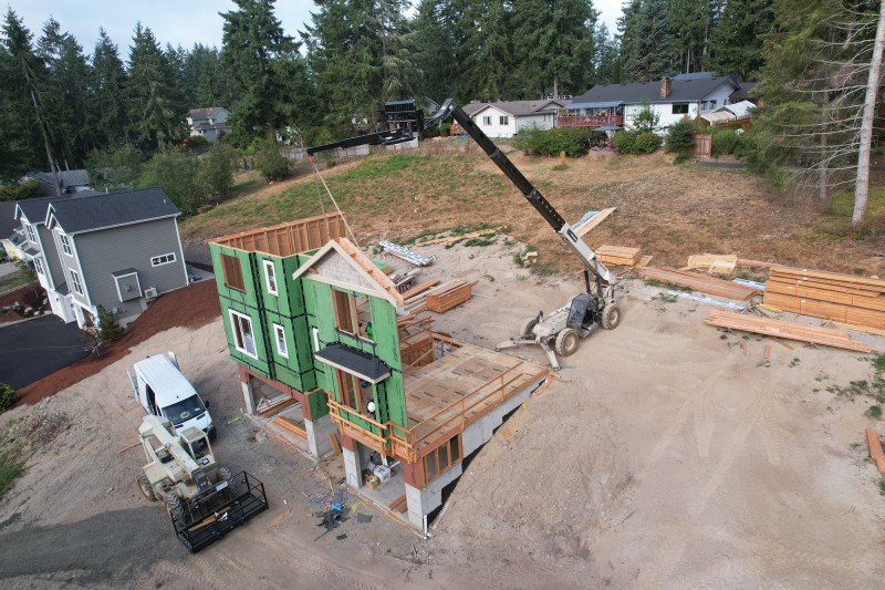
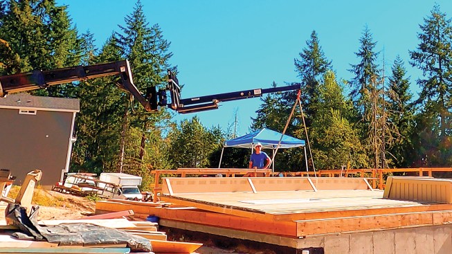
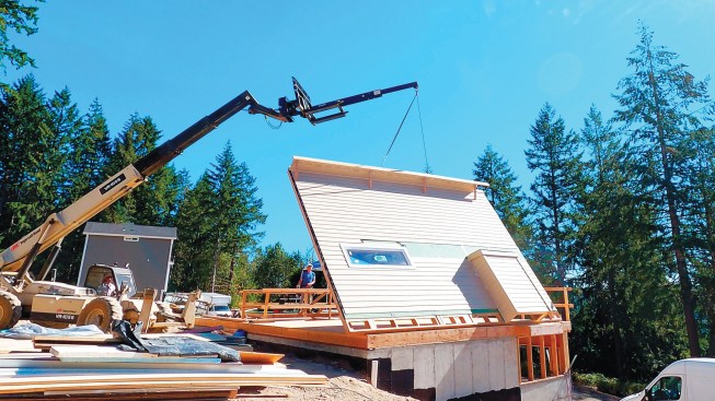
Required equipment. We have two forklifts, either of which can be fitted with our extended-reach truss jib. Rated with a lifting capacity that is far more than our walls weigh, the forklift-mounted truss jib is the key to making balloon framing possible for our crew, though when site conditions prohibit the use of a forklift, we sometimes hire a crane for the lift. Along with owning this equipment, we are forklift- and rigging-certified.
With conventional platform-framed walls, overlapping plates are typically used to tie walls together. When balloon framing, we connect the walls with straps at the top plates, working from a manlift basket. This simplifies layout and framing and makes fitting them together up high much easier.
Wall Framing
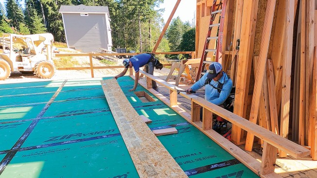
On this project, we ordered 20-foot 2×6 Doug fir studs to frame the 18-foot-high walls, saving the 2-foot offcuts for use as blocking. We cut the top and bottom plates and marked their 24-inch-on-center layout at the same time. When there are king studs on either side of an opening, we double the framing to stiffen up the walls for the lift. When double-studding, opposing the crown helps to straighten the studs; to keep them from bowing, we snapped layout lines after squaring up the wall and tacked the studs to these lines prior to blocking and sheathing.
We used 1 3/4-by-9 1/2-inch LVLs with 2×6 top and bottom plates to build our headers, exactly as we would for a platform-framed wall. At the corners, we used a two-stud California corner to supply backing for drywall.
The author frames tall walls with 2×6 Doug fir studs 24 inches o.c., doubling up the king studs on either side of openings to stiffen the wall for lifting.
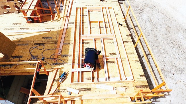
Door and window headers are assembled from 1 3/4-by-9 1/2-inch LVLs with 2×6 top and bottom plates, while 2×6 blocking installed on the flat will support panel edges.
Solid 4x6s are used for both panel edge support and fire blocking where needed.
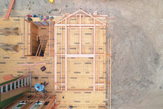
Fully framed from the bottom plate to the gable, this wall is ready for sheathing.
Blocking. As mentioned above, a major drawback of balloon framing in the past was the lack of fire blocking. Platform framing naturally provides separation at the top plates between the walls and the floor system. The subfloor and bottom plate of the wall above also keep the floor separate from upper-floor walls.
To prevent fire from spreading in cavities that run the full height of the wall, we need to block a minimum of every 10 feet vertically and at all ceilings or floors, per code. I like to lay out the blocking working down from the top plates the length of the wall sheathing.
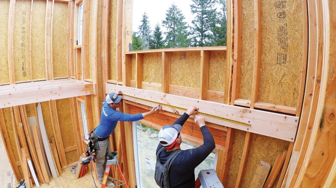
Since the upper floor on this project had 8-foot ceilings, I installed 4×6 blocking 8 feet down from the top of the double top plate, with the blocking centered on the mark. This aligned the fire blocking with the floor sheathing, while also providing edge blocking for the wall sheathing for lateral loads (hanging the sheathing vertically saves blocking). The use of 4×6 stock for this blocking also helped to stiffen the wall during the lift.
Once the first row of fire blocking was installed, I measured down another 8 feet for 2×6 panel edge blocking, which we installed on the flat to allow for insulation. This blocking is needed to meet seismic requirements that the perimeters of the sheathing panels be supported with full 6-inch-on-center nailing.
We also need to install 4×6 blocking wherever strapping is spec’ed; for example, for force transfer around openings, where windows interrupt load path. Here, where we are basically punching a bunch of big holes in shear walls, continuous strapping will need to be installed over the sheathing to seismically reinforce the wall.
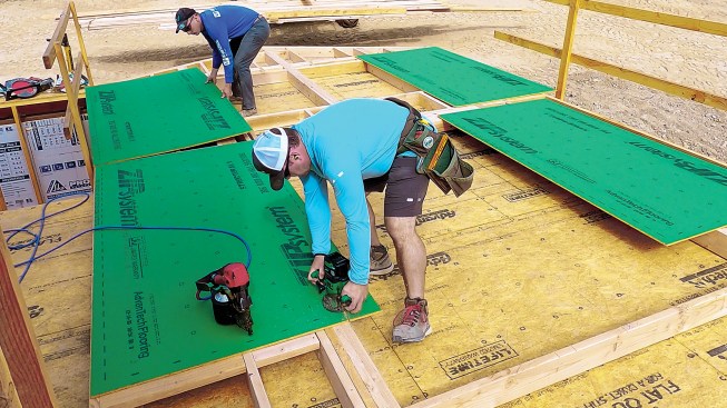
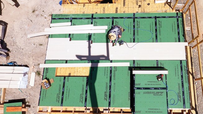
Sheathing. To get better unit pricing and better manage waste, I prefer to order all 4×8 Zip System sheathing, rather than opting for longer panels (which I also think are a little less stable). Installing the sheathing from the top down with the panels oriented vertically allows the bottom sheet—which we install after lifting the wall into place—to span the bottom plate and connect down to the mudsill. This also provides for easy access for installing tie-downs and other hardware.
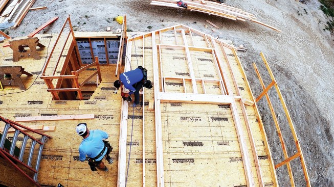
Sheathing is installed from the top plate down, leaving the framing exposed at the bottom of the wall.
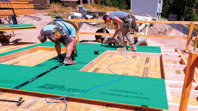
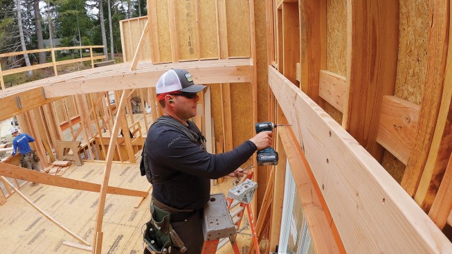
The 4×8 panels are aligned vertically and nailed to the framing 6 inches on-center in the field and along panel edges.
Because we had already installed panel edge blocking, we installed the sheathing railroad style instead of staggering it (staggered sheathing isn’t required by code). With the framing at 24 inches o.c. (rather than 16 inches o.c.), we nailed off the sheathing 6 inches o.c. (instead of 12 inches o.c.) in the field, as well as along the panel edges.
After cutting out window openings and taping all of the seams, we installed continuous strapping over the sheathing where spec’ed in the plans for force transfer around openings. To keep the strapping straight, I like to first snap a line, then nail the strapping to the sheathing with 2 1/2-in. x 0.162 positive-placement nails every 6 inches or so while following the line, so that the strapping lies flat to the sheathing with no bubbles. After cutting the strapping to length, I go back and nail off every hole in it.
The author uses a router to cut out window and door openings.
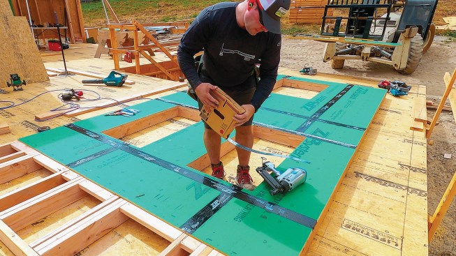
Where required for seismic reinforcement, continuous strapping is installed above and below openings.
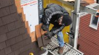
Siding and trim. Inspectors in the municipality where we build circle the walls they want to inspect for shear nailing, and these are always walls with hardware like straps or hold-downs. The rest are fair game, so before we lift a wall into place, we go ahead and install the siding, which in this case—as on most of our projects—was LP SmartSide.
I figure layout from the mudsill and transfer that to the wall, and then we snap lines for each course. Per the instructions for Zip System, I tape (using Zip tape) the side of the wall sheathing to the side of the end stud. Then I snap a vertical line 1 inch in from the edge of the wall so that when the next wall is installed, I can wrap the tape from that wall to the wall being sided. This is also where we align the ends of the siding, which we later cover with overlay corner boards, once all of the walls are installed.
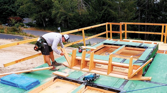
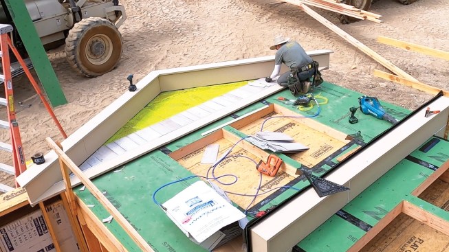
Details such as this window bump-out are easier to build while the wall is flat on the ground.
Once completed, the soffit will act as a strongback as the wall is lifted into position.
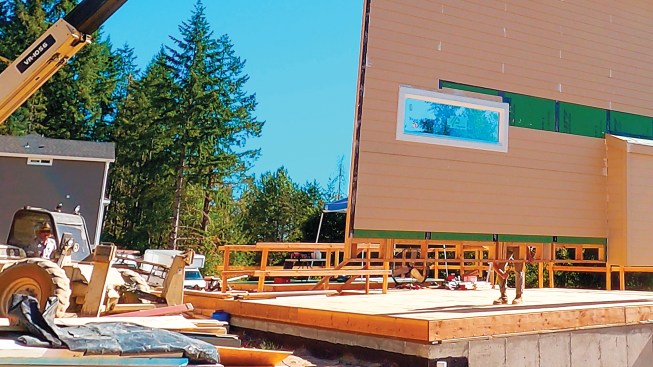
Windows and siding can also be installed before the wall is lifted into position …
… as well as gable rake trim.
Installing windows with the walls flat on the deck is easy (I first learned how to do this in the early 1990s and show how to do this on my YouTube channel). Installing window trim and drip-cap flashing is much easier at this point than later, off ladders or scaffolding. Since we are using Zip System, the flashing details are simple.
One negative to siding on the ground is that we work bending over. While that is a fair concern, we do this only a few days out of the month a few times a year and it’s worth it. We trade off as much as possible so one person isn’t doing all the work bent over, and since we save so much time, we tend to take a few more rest breaks. Often, it takes less than an hour to side the wall. For example, it took us less than two hours to install 100 pieces of SmartSide on the big wall shown here (see photo, above).
Later, when the walls are up and we finish the siding, we’ll just work up to the last course that we had installed before lifting and tuck the last pieces underneath and face-nail them. I like to use Big Stretch sealant on the face nails, which we touch up with paint later.
Closed soffits are easy to install when the wall is flat; they just need to be finished off when we install corner boards. I draw out the overhang to determine the exact location of the subfascia, then nail a 2×6 ledger to the wall and a 2×6 subfascia to LP SmartSide 16-inch-wide vented soffit to create the soffit assembly, with blocking on approximate 4-foot centers spaced so that the blocking won’t interfere with the rafters. Another benefit to installing the soffit on the flat is that it acts as a strongback during the lift.
Lifting and Bracing
To prep for the lift, we fasten specifically engineered and fabricated brackets to the top of the wall. In addition to following the fastening schedule required for the brackets, I’ve started adding SST SDWS screws through the plate to the studs on either side of the pick point for a little extra reinforcement.
Braces nailed to the soffit and to the wall help reinforce the assembly during the lift.
Toenails driven through the plate into the floor sheathing keep the wall from sliding while it’s raised.
Once the wall is vertical and suspended up off the deck, a worker removes the toenails before the wall is lowered into place.
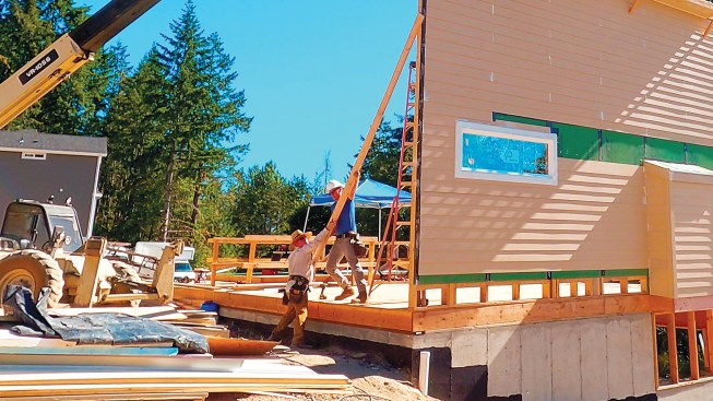
After the plate is fastened to the deck with structural screws, the crew installs 2×6 braces to hold the wall in position, also with structural screws.
As each wall is raised and installed, it acts to brace the adjacent wall.
Once the walls are in place, metal strapping installed from a manlift basket is used to connect the top plates together.
Wind is always a factor when setting walls; we can’t lift when it is too windy. To keep the wall section from sliding around while we hoist it up off the deck, we toenail the bottom plate to the deck prior to the lift. Then, once the wall is vertical and suspended, we pause to remove these toenails from the plate.
Lifting walls is dangerous, and we work slowly and carefully as one of us operates the forklift and manipulates the boom while the other signals the forklift operator and helps guide the wall into position. We locate one corner first, and then fasten it to the layout line snapped on the deck with SST SDWS structural screws, which can be removed if the wall position has to be readjusted later. Then we ease the rest of the wall into position so that the plate is just shy of the line, and fasten it to the deck with more structural screws.
Once the wall is in place but still supported by the lifting straps, we brace it with 20-foot 2×6 braces fastened to the framing with 6-inch structural screws. We plan the order that we frame the walls so that there is room on the deck to build them and so that we can tie adjacent walls together as we raise them. They are basically giant sails, so we brace them with long structural screws driven into the framing rather than with cleats and nails, and we tie them together with strapping across the top plates. Then we move on to the next wall.
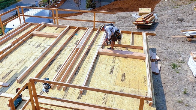
Floor Framing
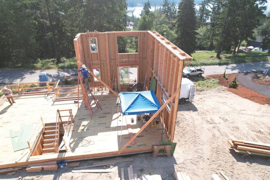
Once the walls are in place, we frame the floor system similar to how we would a deck, starting with a ledger that is fastened to the wall framing. Remember, the ledger is supporting only floor loads, not roof loads, so this approach provides plenty of strength. The ledger also acts as fire blocking that separates the floor system from the wall cavity.
The floor system is hung from ledger boards that are fastened to the wall framing with structural screws.
The ledger acts as fire blocking between the wall cavities and floor framing, and helps pull the studs into plane.
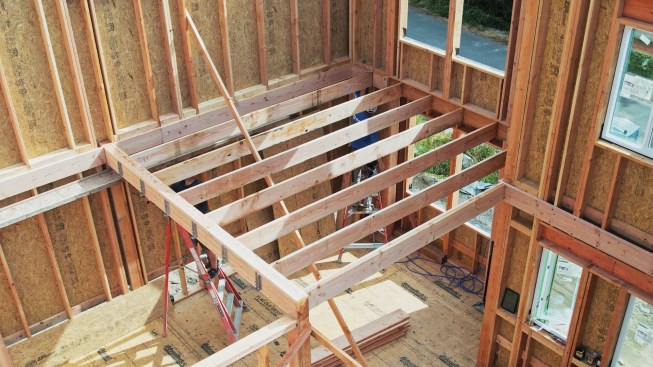
An I-joist temporarily screwed to the studs also helps flatten the walls during ledger installation.
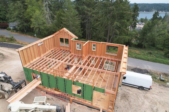
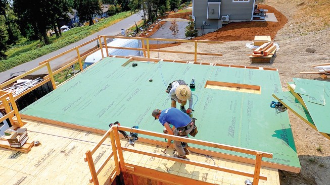
After the floor system is in place, construction can proceed conventionally.
To help position the ledger, we cut a 2-by to the height of the back wall plate (109 1/8 inches on this project) and used the 2-by to mark that elevation at all of the corners. Then we worked around the walls, tacking the ledger in place with nails and then fastening it to the 2×6 studs using 5-inch-long Simpson Strong-Tie SDWS timber screws. These screws are designed for deck ledgers, and our engineer specifies the spacing. We always use more than spec’ed because we use the ledger to help pull the studs into plane.
To flatten the wall until the floor is sheathed, we screw an I-joist on edge to the studs just below the ledger. Our order of operation is to install the ledger and then the I-joist “strongback” before bracing the walls plumb and straight. We find that we need fewer braces using this method.
Then we are ready to start installing floor joists. We typically toenail them into place and add hangers later, unless there is an intermediate beam. In that case, I like to install the hangers before lifting the beam into place.
Photos by Tim Uhler