One of my dreams has been to build a home with wood harvested from my own land. Last year I finally had the opportunity, when my wife and I designed and built a new home on a 25-acre lot in northern Vermont. We had already cleared a building site, and we used a portable sawmill to mill more than 20,000 board feet of lumber from the mixed hardwood and softwood trees we had harvested. I’m a carpenter and cabinetmaker at heart and was anxious to put all that wood to use – as siding, trim, flooring, and cabinetry. But I was more concerned about the home’s energy use and long-term performance. We wanted a comfortable, low-maintenance house that would be easy to heat, even in our cold and not particularly sunny climate. By building a well-insulated, airtight shell, we were able to approach net-zero energy, achieving a final HERS rating of 4. Here’s how we did it.
Well-Insulated Foundation
I’ve found that when a customer wants a finished basement, ICFs are the most cost-effective way to build the foundation walls; they’re easier to finish than poured concrete walls and can be installed by my own crew. For my house we used 11-inch-wide Amvic forms (amvicsystem.com, 877/470-9991), which have 2 1/2-inch-thick EPS sides and a nominal R-value of about 25 after they’re poured.
Footings. We formed the footings with FastFoot fabric membrane (888/303-3278, fab-form.com), a woven polyethylene material that gets stapled to 2×4 screeds that are attached to form stakes (see Figure 1). An important advantage of the fabric is that its impermeable polyethylene coating blocks ground moisture from wicking up into the footing and foundation wall. Because the product saves form lumber, it also helped earn LEED points for the project.
Figure 1. Fabric footing forms remain in place after the concrete is poured, creating a capillary break between the ground and the footing (top). R-26 ICF forms were used to build the foundation walls (middle), which were wrapped with an additional 2-inch layer of EPS, then waterproofed with a foundation-grade peel-and-stick membrane (bottom left). The basement slab is insulated with two layers of 2-inch EPS foam, with a vapor barrier sandwiched in between (bottom right).
Slab. The basement slab is insulated with two layers of 2-inch EPS foam, for a total R-value of 16. We laid the first layer over a 6-inch base of compacted stone, followed by a 6-mil poly vapor barrier, which laps over the piers and footings. The second layer of EPS protects the poly and is sealed to the ICF walls with canned spray foam.
We also added a layer of 2-inch EPS to the exterior of the foundation wall, using spray foam to tack the boards in place, then securing them to the ICFs’ plastic ribs with ring-shank nails driven through plastic washers. This gives a total foundation wall R-value of about 32. The walls are also protected from moisture by a layer of Colphene ICF peel-and-stick waterproofing membrane (800/356-3521, soprema.us).
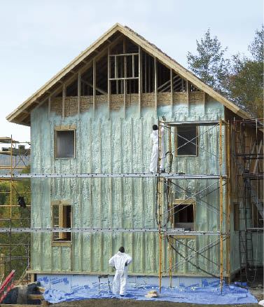
A continuous layer of closed-cell foam seals and insulates the sheathing, effectively placing all structural framing members inside the thermal envelope. XPS spacers behind the exterior 2×4 studs further reduce thermal bridging through the exterior foam layer.
Framing for Foam
A few years ago, I attended a presentation by John Straube of Building Science Corp. in which he described how he stripped the siding off an existing house, screwed 2×4 studs on edge through plastic spacers into the existing sheathing, and then filled these exterior stud bays with closed-cell spray foam insulation (see Research Report-0903, buildingscience.com). The plastic spacers allowed the foam to flow between the studs and the sheathing, strengthening the assembly and minimizing thermal bridging. The closed-cell foam also acted as a drainage plane, requiring no additional building paper.
I decided to use a similar detail on my own house, knowing that my crew would be learning a method we could put to use on future energy-retrofit projects. Instead of plastic spacers, we used lengths of rigid foam to space the 2x4s off the sheathing. We first framed 2×6 walls (the original plan was to fill them with dense-pack cellulose) and sheathed them with OSB. Because these walls would eventually be 13 inches thick, we splayed the window openings by 30 degrees, using beveled 2x8s as trimmers, to allow more light into the rooms. We used two-stud corners and other advanced framing techniques to minimize thermal bridging where possible.
We let the 1/2-inch OSB overhang the bottom plate by 14 1/2 inches so that it would lap over the rim joist and mudsill, which had been inset 1/2 inch from the outside face of the ICFs.
Exterior studs. Once each wall was framed and sheathed, we installed the exterior 2x4s, placing them on the same 16-inch centers as the interior studs on top of 1 1/2-inch-wide strips of 2-inch-thick XPS foam (Figure 2). XPS has more compressive strength than EPS, but we used it mainly because it cuts easily on a table saw without crumbling. We fastened the 2x4s to the interior studs through the foam with 8-inch-long HeadLok screws, which have a flat head and don’t require counterboring. To make it easier to accurately drive the long screws and hit the interior studs, we predrilled holes about every 2 feet.
Figure 2. After framing and sheathing the 2×6 walls, the carpenters screwed 2x4s to the exterior through 2-inch foam strips and added door and window bucks (top). Lifting jacks were needed to raise the heavy walls into position (bottom).
On the first floor, the exterior studs extend past the top of the foundation by 6 inches, creating an airtight overlap at the rim joist. On the south wall, however, the grade drops away, leaving about 4 feet of the foundation exposed. Here, we extended the exterior studwall system over the foundation’s EPS cladding by screwing horizontal cleats to the ICF ribs, then notching the 2×4 extensions and screwing them to the cleats (Figure 3). We also had to add a layer of Typar over the EPS to prevent the closed-cell spray foam from chemically reacting with the EPS and degrading it.
Figure 3. The exterior walls were framed so that, when lifted into place, the OSB sheathing and the outer 2×4 studs cover the rim joists (top), providing continuous bays for spray foam from the foundation to the truss top chords (bottom).
Window and door bucks. To provide solid attachment for doors and windows, we built bucks out of 5/4 by 6 3/8-inch stock. The bucks are pocket-screwed from the outside through the sheathing into the interior framing and fastened from the inside with screws driven through the beveled trimmers. They stand 7/8 inch proud of the outside face of the exterior studs, flush with the shiplap siding that we had milled from the white pine on site. We also pocket-screwed 2-by blocking on the flat above and below each window opening to provide solid backing for flashing and trim.
Roof. We framed the 9/12-pitch roof – a good angle for PV panels in our climate – using attic trusses with 24-inch-high raised heels so we could blow plenty of loose-fill cellulose insulation into the attic (Figure 4). The trusses also have raised center chords that support a set of planks running down the center of the building, which gave the solar installers a 30-inch-wide by 6-foot-tall walkway above the cellulose from which to work.
Figure 4. The roof was framed with raised-heel trusses, which allow for 24 inches of blown cellulose under the top chords at the plates (left). The trusses also have raised bottom chords down the center, creating a comfortable passageway and work platform for mechanical contractors. Dropped gable trusses support the 2 1/2-foot-deep gable overhangs, shown here being blocked (right).
To contain the cellulose in the attic, we extended the sheathing up the gables an additional 4 feet. At the eaves, the sheathing covers the raised heels of the trusses and is notched around the top chords, allowing room for a ventilation baffle so the soffit can vent into the attic.
Exterior Spray Foam
After the framing was complete, our insulation sub sprayed the exterior stud cavities with 3 1/2 inches of Demilec HeatLok Soy (877/336-4532, demilecusa.com), which has an R-value of 7 per inch. Because of the XPS spacers, this leaves 2 inches of the stud cavities unfilled, creating a drying space behind the siding (Figure 5).
Figure 5. After the exterior stud bays were sprayed with 3 1/2 inches of closed-cell foam, workers let in blocking for a future addition, then covered the foamed stud bays with housewrap (top). The windows are fastened directly to the bucks, then flashed to the housewrap with flashing tape (bottom left). The window openings were framed with a 30-degree flare to allow in more light (bottom right).
The exposed rim joists in the basement and first story were also sprayed, along with the raised heels in the attic (Figure 6). The insulation contractor we work with is meticulous about checking moisture content before spraying; this is particularly important anywhere moisture could become trapped behind closed-cell foam, which has very low moisture permeability. So, for example, he made sure the OSB sheathing was dry before spraying foam on the inside, just as he would before spraying foam against roof sheathing in a hot-roof application.
Figure 6. The truss heels and other framing joints were first air-sealed with closed-cell foam in preparation for blown-in cellulose (left). Note the site-built baffles behind the foam – pieces of plywood over strips of wood along the top chords – which allowed for 30 inches of insulation without blocking the soffit vents. To support all that cellulose, the author installed OSB rather than drywall on the bottom chords of the trusses (right). Sealed with tape and mud, the OSB provides an airtight seal between conditioned space and the attic and solid backing for the tongue-and-groove wood ceiling that followed.
Ventilation. The bottom of each exterior stud bay is vented with a strip of 3/4-inch Coravent, which will keep bugs out while allowing the cavity to drain and ventilate. At the top of the wall the stud cavities connect to the soffit, which is vented to the outside.
Windows and Doors
We found there was no easy way to flash window and door openings back to the foam drainage plane. So instead we wrapped the walls with Typar stapled directly to the exterior studs, and treated the housewrap as a primary drainage plane. Then we used membrane flashings to integrate the windows and doors, taping the side and top flanges to the housewrap – but not the bottom flanges. This should allow any water that might get into the opening to drain out of the assembly. Moisture that gets into the wall above windows and doors will have a harder time escaping, but we’re confident that with the large roof overhangs, any accumulation will be insignificant. Plus there’s a 2-inch drying space, so moisture should be able to evaporate before it can cause a problem.
After siding the house, we pre-assembled the window and door casings and installed them as units. We sealed the casings and drip caps to the siding with Geocel 3300 polyurethane sealant (800/348-7615, geocelusa.com).
Air-Sealing and Interior Insulation
Once the exterior was complete, we grabbed caulk guns, spray foam, and buckets of duct-sealing mastic and went to work sealing up any gaps we thought might leak – joints around headers and between double studs and plates, as well as all wire and duct penetrations through the framing. Then the insulation subcontractor came back with a blower door and pressurized the house for a couple of hours while we used smoke pencils and an infrared camera to examine every square inch of the shell. Joints between the interior and exterior walls around door and window openings were one of the few areas that consistently needed attention, but we also pinpointed other random leaks. Preliminary blower-door testing showed an air leakage rate of about 600 cfm50 – not bad, but not as low as we wanted.
Though our original plan was to dense-pack the interior walls, our insulation contractor offered to spray them instead with another 3 1/2 inches of Demilec for about the same price. This added some R-value to the original plan and provided tight seals around duct chases and other penetrations. As a result, our final blower-door numbers dropped to 384 cfm50. This translates to 0.1 cfm50 per square foot of above-grade surface area, or .83 air change per hour.
Mechanicals
Our Manual J calculations predicted that the design heat load for the 2,000 square feet of main living area would be about 22,000 Btu; adding the basement and office space above the conventionally framed garage to the calculations brought the total design heat load to almost 60,000 Btu. To allow us to efficiently heat all three zones with one system, we installed a Buderus GB142 propane-fired modulating condensing boiler (800/283-3787, buderus.com). This is a 96 percent efficient wall-mounted unit with a microprocessor control, an outdoor temperature sensor, and variable output ranging from 22,500 to 75,000 Btu (Figure 7). The hydronic system has a total of five zones – one for each of the two upstairs bedrooms and one each for the main floor, basement, and garage office – and uses individually controllable panel radiators to deliver the heat. Mechanical whole-house ventilation is supplied by a Venmar EKO 1.5 heat-recovery ventilator (800/567-3855, venmar.ca), which is also zoned.
Figure 7. The home’s heat is supplied by a Buderus wall-mounted propane boiler (top left). The condensing unit has variable output between 22,500 and 75,000 Btu, depending on how many of the five zones are calling for heat. The 80-gallon Superstor Solar storage tank (top right) receives hot water from two roof-mounted solar thermal collectors (bottom); backup is provided by an electric heating element. To the left of the storage tank is a Venmar EKO 1.5 heat-recovery ventilator.
We installed a pair of roof-mounted flat-plate solar hot-water collectors and expect that they will supply at least 50 percent of our domestic hot-water needs. Water heated by the collectors via a heat exchanger is stored in an 80-gallon SuperStor tank (800/323-9651, htproducts.com), which also has a backup electric heating element to take advantage of the 7-kilowatt grid-tied PV array up on the roof. Since we’re in a rural area with frequent power outages, our net-metered electric system is backed up by both a generator and DC batteries.
Cost considerations. We spent $18,500 on spray-foam insulation – slightly more than I had estimated for dense-packed 2×6 walls wrapped with 4 inches of rigid foam. But based on our blower-door test results, I’m convinced that spray foam provides better air-sealing than even our most carefully detailed rigid foam jobs. Whether it’s sprayed on the interior or the exterior, I’ll continue to use it on both new construction and retrofit jobs.
Tom Moore is a building contractor in Underhill, Vt.


