The slight camber on the posts may have seemed a minimal gain fo…
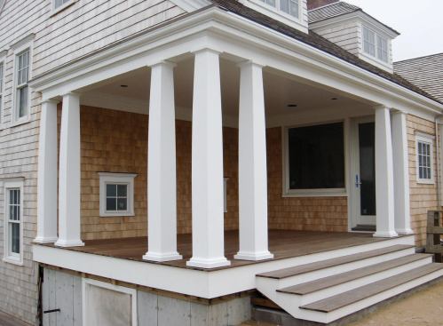
Our company operates a woodshop in Chatham, Mass., where we design and build a variety of products from custom cabinets to one-of-a-kind pieces. We were recently hired by a local home builder, Steven Nickerson, to make several unusual porch columns for a custom home he was building on a site overlooking the ocean. The inset porch has living space above, which is supported by three structural posts that carry a heavy engineered lumber beam. The design called for three PVC columns to conceal the structural posts, along with four identical columns that would be purely decorative, including two pilasters set into the walls at the ends of the porch. Steve’s crew had carefully laid out the structural posts and had already finished the trim work, so it was critical that our columns meshed with their work. We fabricated the columns in our shop, and installed them on site over the course of about four weeks.
Making a Pattern
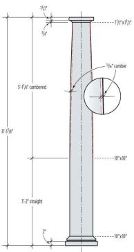
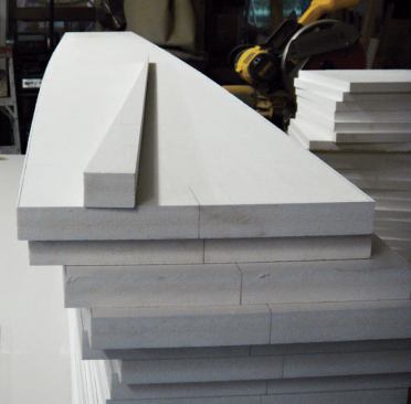
The architect provided precise CAD drawings for us to work from (see slideshow). The columns were to be 10 inches square from the base to a height of 3 feet 2 inches, then taper to 7-1/2 inches square at the cap. One peculiarity was that the taper was not a straight line, but followed a gentle camber that bowed out 5/16 inch at the midpoint. The corners were to be mitered so that no edge grain showed. Once we had a clear idea of the design, we ordered a stack of 1×12 PVC boards and set to work.
We decided to cut the tapered miter using a router and a full-height 1/2-inch MDF pattern. To scribe the taper, we marked two points on the MDF – one 3 feet 2 inches up from the bottom, at the top of the straight section; and a second at the very top, 1-1/4 inches in from the edge, or half the difference between the 10-inch-square bottom and the 7-1/2-inch-square top. We drew a straight line between the two points and marked the 5/16-inch outward camber.
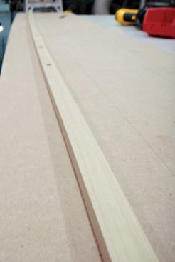
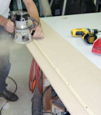
At this point in a curved design, we would normally swing an arc to draw a precise line. But some quick arithmetic showed we were working with a radius of almost 125 feet, making this method impractical. Instead we ripped a 3/8-inch-thick strip from a piece of straight-grained 3/4-inch poplar and used this stick to physically bend a nice smooth curve. We traced what would become the cut line onto the MDF, then moved the poplar stick inward the correct distance to act as a fence for the router base and secured it with screws. Before routing the pattern, we first trimmed to within 1/16 inch of the cut line, then used the router to create a smooth, square edge.
Cutting the PVC
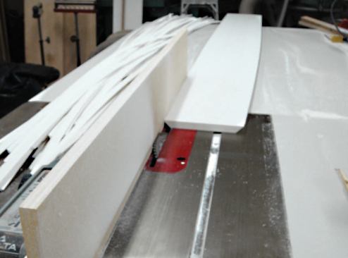
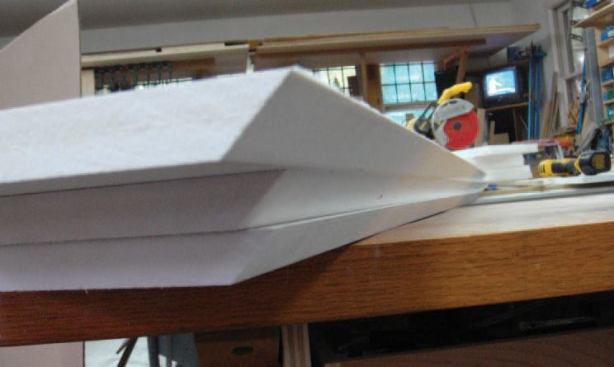
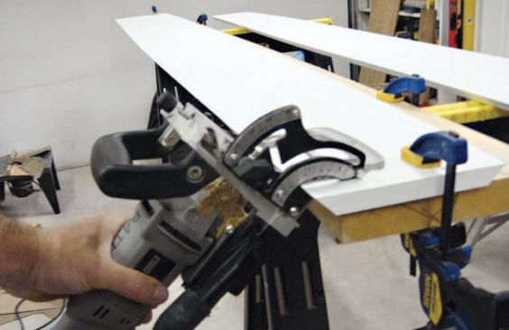
Next we needed to rough-cut the tapered camber onto the PVC stock. After chopping the 1x12s to length and straightening them on the table saw, we centered the pattern on each piece and traced the cambered line along one edge, then flipped the pattern over, realigned it, and traced a symmetrical line on the opposite edge. We then cut to within 1/16 inch of the line to get rid of the waste; this left a square edge slightly proud of the final cut line. To remove additional waste before the final cut, we next ran the edges through the table saw, with the blade set at 45 degrees and the fence on the left side of the table. We set up a sacrificial fence into which we raised the blade, just high enough so that we could remove most of the waste from the miter while still leaving about a 1/16-inch flat shoulder to ride against the fence. We were now ready to cut on the money.
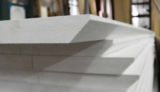
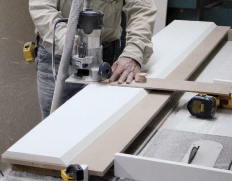
Final edges. We again aligned the MDF pattern on the PVC, this time securing it with screws placed at the ends where moldings would later cover the holes. We set up the router with a 45-degree bottom-bearing chamfer bit and mounted it on a wide auxiliary base for stability. It was then a matter of guiding the router along the edge of the MDF jig to cut a perfect miter.
Joinery
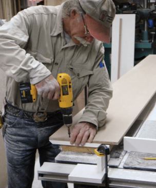
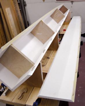
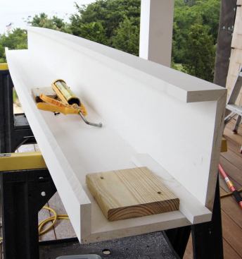
Rather than a locking miter, which would have complicated an already complex cut, we decided early on to use biscuits for alignment when we glued the columns together. After cutting the biscuit slots, we built a cradle to help the glue-up go smoothly. We made 90-degree notches in some pieces of scrap 3/4-inch plywood and fastened these in an upright position to a couple of 2-by planks. We set two of the cradle blocks at equal height to support the lower straight sections of the columns and a third block at an elevation to support the narrower top of the column. We also cut four plywood squares matched to the column’s inside dimension at specific points along the taper and used these to keep the assembly square during glue-up.
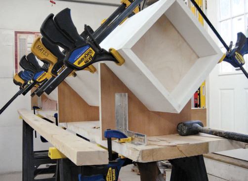
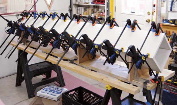
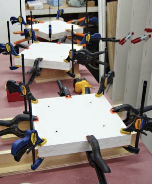
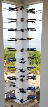
Glue-up in halves. We dry-fitted the biscuits and assembled the first two sides in the cradle without glue, then positioned the squaring blocks. We added a third side, also biscuited but unglued, then laid out the rest of the biscuits we would need and set out our clamps – Irwin Quick-Grips and McNulty Specials – along the length of the cradle. At this point we were ready to glue the first corner. We used separate cans of Azek PVC cement for speed, quickly spreading the cement along the edges to be joined and inserting the biscuits. We dropped the fourth side into place, aligned the ends, and gently snapped the two glued sides together. Even though we were only gluing one corner, we placed clamps the entire length of the column on all four sides to ensure that they stayed square. After the cement set, we removed the glued-up half-column from the cradle and repeated the process until we had made 13 half-columns. We substituted one of these half-columns for the original two sides in the cradle, then glued together the last half-column, which gave us the seven pairs we needed.
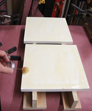
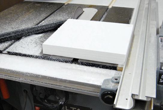
During this process, while the glue was drying, we worked on the 1-1/2-inch-thick caps and bases, which we laminated from two pieces of 3/4-inch PVC. We rough-cut the pieces 1/4-inch larger than final size, then cemented and clamped them together, working off some simple clamping stands. We also added screws, placing them where the columns would hide them. Once the cement was dry, we trimmed the parts to size on the table saw.
We assembled the two nonstructural columns in the shop, this time quickly gluing up the remaining two sides at once. The columns that were to enclose the structural posts required final assembly on site, so we left them in halves. We also cut their caps and bases in half, then rejoined the pieces with temporary pocket screws before cutting them to finish size. The last two columns were pilasters, designed to appear as full columns set directly into the corners of the house. Since one corner would have to be cut out entirely when these columns were scribed to the house, we only glued up three corners in the shop and left the fourth corner loose.
Field Installation
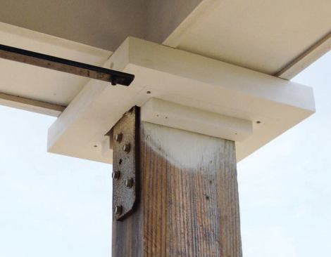
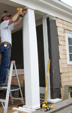
We started with the cap of one of the structural column surrounds, first removing the temporary pocket screws and separating the two halves, then cutting out the notch to allow it to fit around the post and metal beam ties. We glued and clamped the halves around the post, then, after the cement had set, precisely positioned the cap and fastened it to the bottom edge of the beam fascia with stainless steel screws, again placing the screws so the moldings would hide them. To prevent water infiltration, we glued small strips of PVC in the space between the beam soffit and the cap.
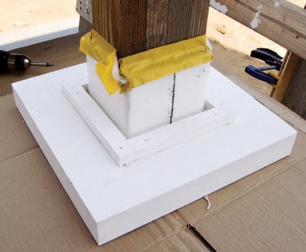
We repeated the process for the base, elevating it slightly by tacking small pads of 1/4-inch PVC to the bottom corners to avoid trapping moisture and rotting the wood deck. We carefully plumbed down from the cap before fastening the base through the pads directly to the decking with stainless steel screws.
Next, we added cleats to both the cap and the base just inside the final position of the column sides. With the cap and base secured, it was simply a matter of repeating our shop glue-up procedure, with the column halves now oriented vertically around the structural posts. After the cement set, we sanded the columns smooth and fastened them to the cleats on the base and cap with stainless steel screws.
Nonstructural Columns
Once the three structural column surrounds were installed, we were able to position the other columns to match their spacing. Since there were no posts to contend with, we attached square cleats of 3/4-inch PVC to the cap and base, sized slightly smaller than the inside column dimensions. After tacking on the 1/4-inch pads, we set the column on the base, put the cap on top, and slid the loose assembly into the proper position. When our spacing was correct, we fastened the cap to the beam fascia, the base to the decking, and the column sides to the cleats.
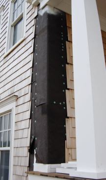
Pilasters. We first laid out and scribed the caps and bases of the two pilasters, then fastened them as we had done with the other columns. Scribing these columns to the house presented a bit of a problem, since we were unable to plumb the tapered cambered sides as we normally would, using a level. Instead, we drew vertical lines down the center of the sides to use as a reference. We measured and rough-cut the back corner of each column to within 1/8-inch with a circular saw, then scribed the two edges to the house. We installed PT backers on the inside to catch the ends of the railings, and fastened vertical cleats on the house to position the pilasters and give us something to screw to. We then gently stretched each column open, snapped it over the cleats, caulked the edges, and fastened it so the cedar shingles (which the framers had left off at the pilaster locations) would conceal the screws.
Finally, we installed the moldings at the cap and base, concealing our strategically placed installation screws. After a final sanding, the decorative columns were ready for paint. We built the railing sections in the shop while the columns were being painted, and returned a few days later for a quick installation.
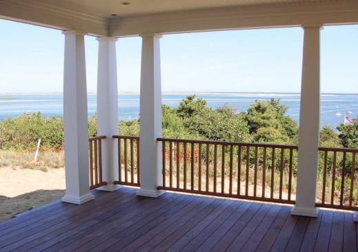
The slight camber on the posts may have seemed a minimal gain for the amount of complication it added to the project, but once the columns were finished and in place, we found that the detail added an unmistakable elegance, especially when viewed against the backdrop of the Atlantic Ocean.
Dan and Luther Bates operate Bates Woodwork in Chatham, Mass.


