Restoration of vintage Victorians is a booming business in the Boston area. As a stair specialist, I’m frequently called in to design, build, and install new, historically correct staircases. The catch is that they also have to meet modern building codes.
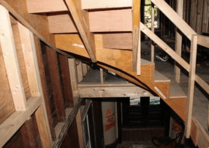
The project I’ll discuss in this article began with a completely gutted, 1880s-era three-story house with only the original stair from the first to the second floor left standing. Because the carpenters had to climb ladders to access the third floor, they were understandably eager for us to begin.
Unlike many stair shops, we often build custom stairs on site, in stages. We first build the rough carriage and install 3/4-inch plywood subtreads and risers, which are permanently glued and screwed in place. For subtreads and risers, I like to use poplar industrial plywood, which holds screws well and stays reasonably flat. Arauco and lauan plywoods are also good.
Next, after the mechanicals and insulation are in place and the flat plaster work is completed, we install finished trim, skirtboards, risers, treads, and moldings. Last, when other finish work is winding up and the painters have started, we install the balustrade. Done this way, the job has a safe, usable stair that can be wired and plastered without the need to protect any finished surfaces throughout the rough phases of the job.
Winder Rules
For this particular job, the architect’s drawing showed a new stair winding up to the third floor, a design appropriate for the period but one that I immediately knew wouldn’t meet code. As drawn, the U-shaped stair called for three 30-degree winders at each right-angle turn. While such stairs are typical in homes built before, say, 1960, they’re no longer allowed by code. Old-style winder treads typically taper to a point at the outside corner, whereas current building codes won’t allow any part of a tread to be narrower than 6 inches. This is too bad, because these traditional stairs are comfortable to climb, look good, and take up less space. Nonetheless, we had no choice but to redesign the stair to meet code.
The walk line. Those old stairs are comfortable to climb because they follow one of the most important rules of stair safety: The net run of the treads, measured at the walk line, should be constant from the top to the bottom of the stair. The walk line is an imaginary line that represents the path the center of your body takes when climbing and descending a stair — typically about 15 inches in from the centerline of the handrail. Try it: Stand on a stair with your hand on the handrail, center the end of your tape measure on the handrail, and check the distance to your belt buckle.
When designing winding stairs, this rule — plus making certain that all risers are the same height — is critical. When your feet move the same height and distance forward with each step, the tendency to stumble on a stair is greatly reduced. That’s why the walk line is my first consideration when I draw a stair in plan view.
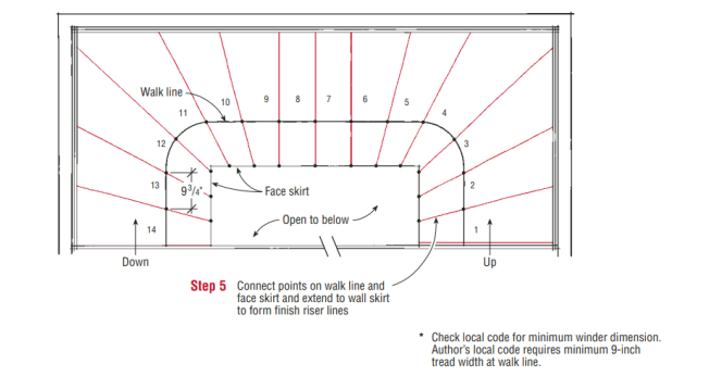
Though I prefer to lay out winders with a 15-inch walk line, my local code uses 12 inches, and requires a 9-inch minimum tread width at the walk line. So to pass inspection I have to make sure I meet that requirement. For the stairway shown here, which was only 36 inches wide, I used a 12-inch walk line for layout.
Work Full-Scale
The most important piece of advice I can give to a carpenter tackling a stair project is to design it completely before you start cutting lumber. When I bid a complex stair like the one shown here, I include at least 16 hours for design and layout.
When laying out stairs, I always start with the finished surfaces and work backward toward the rough structure. Many dimensions of the rough frame won’t be obvious until you know how far they are behind the finished surface. And there’s no sense in even starting the layout until you know the thickness of the finished flooring: It’s not always 3/4 inch, and it may vary from one level to the next. It’s also important to know the finished tread thickness. You’ll avoid the most common error picked up by building inspectors — uneven riser heights — by nailing down all dimensions at the beginning.
I use full-size layout for any stair more complex than a straight run. You need full-size patterns to make the winder treads, and full-size details of the important areas around the newels are essential to get every component in the proper position. Full-size drawings are also necessary to lay out the stringers for winding stairs.
Drawing full-size doesn’t require any special equipment — I use a drywaller’s T-square, a framing square, a long level for a straight edge, a tape measure, a compass to draw small radii, and a trammel point on a stick to draw big circles. Eighth-inch-thick lauan plywood is an inexpensive, smooth material to draw on, and when one project is done, I paint the sheet with white primer and reuse it.
The Story Pole
Architect plans can be unreliable, so I always mark accurate site measurements on a story pole — a clean length of 1-by lumber 1 to 2 inches wide and a little longer than the floor-to-floor distance. The story pole provides an accurate, full-size stair elevation condensed onto a tall stick. By working things out on the story pole first, I eliminate the cumulative error that can otherwise result from rounding riser heights to the nearest 1/16 inch. Even a 1/32-inch deviation per rise can turn into a 1/2-inch disaster when multiplied by 15 risers.
I label the pole’s bottom end for reference and square the thickness of the finish flooring across it, up from the butt. I begin by marking the rough-to-rough floor distance directly on the pole. The two points, where the stair begins and ends, usually aren’t directly over each other, so I use a laser level (Stabila LAX 100, 800/869-7460, www.stabila.com) to find the difference in elevation. I stand the pole in the stairwell at the starting riser location and shoot a level reference line over to it from the top riser location. The floor in a rehab often is not level, so I always work from the walk line. While I’m at it, I also mark corresponding laser line marks on the surrounding stairwell walls for later reference when installing the stringers. Then I put away the laser — I won’t need it again.
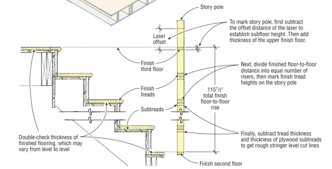
After making sure of finish floor thicknesses, the author lays out a story pole for the stair, first using a laser level set at the walk line to establish reference points.
Next, after laying the pole flat, I subtract the offset distance of the laser beam (the distance of the beam above the subfloor). This mark establishes the subfloor height. Then I add the thickness of the upper finish floor above the subfloor reference line. This gives me the finished floor-to-floor distance of the stair at the walk line, which I quickly divide into an even number of risers using a Construction Master calculator. I mark these on the story pole — these are the finish tread heights — and then subtract the tread thickness, as well as the 3/4-inch thickness of the plywood subtreads, to get the rough stringer level cut lines.
The final steps of this stage consist of checking diagonals on the rough stair openings to see whether they’re square and checking the walls for plumb and flatness. There isn’t a lot I can do about out-of-plumb-and-square conditions, other than to accommodate them. If I don’t design the stair to match the existing conditions, I’ll have a real struggle on my hands, trying to make the pieces fit together.
A Drawing That Works
Most plans provided by architects show half of the stair on the lower floor plan and half of the stair on the upper floor plan, which doesn’t help me much. Both my scaled stair plan, which I use as a presentation drawing for the GC and client, and my full-scale layout show each floor-to-floor stair run as a unit.
I locate the handrail centerline — typically half of a baluster’s thickness in from the face-skirt line — and offset the walk line 15 inches from there. I then divide the walk line into even tread segments, relying on the formula 2 risers + 1 tread = 25 inches. On a residential stair, the risers must measure between 6 1/2 and 8 inches; as riser height increases or decreases, the tread run changes accordingly.
The total floor-to-floor rise for this stair was 115 1/2 inches. I broke it down into fifteen 7 11/16-inch risers and fourteen 9 3/4-inch-wide treads, measured at the walk line.
My next step is to mark tread divisions on the face-skirt line by dividing its total length into equal segments. Depending on the total run and configuration of the stair, there may be a number of “common” treads — full-width treads that occur in a straight section of the U. You can determine this by trial and error, trying to keep the narrow ends of the wedge-shaped treads as close to the minimum 6 inches as possible. The stair shown here had two commons.
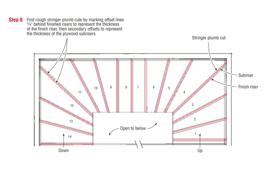
With the tread spacing marked equally along the face-skirt line, I connect those marks to the divisions along the walk line and extend each line to the wall. This gives me the complete finish riser line for each step; from there, it’s easy to mark the back of the 3/4-inch finish riser, then the back of the plywood subrisers, which tells me where the rough stringer plumb cuts go. (I also add other details to the drawings as needed — nosing, wall skirts, newels, baluster, and railing.)
Stringer Layout
I use LVL for stringers; it’s 1 3/4 inches thick and very stable, and comes in a variety of widths. Because the winders cross the stringers at different angles, the stringer shapes become complex and require wider-than-normal stock. For this stair, I used 16-inch-wide LVL.
All the information I need to lay out each stringer is right on my full-size plan. I draw 3/4-inch offset lines behind the finished risers and inside the skirtboard line to represent their respective thicknesses. Then I draw secondary offsets 3/4 inch behind those lines to represent the thickness of the plywood subrisers. I draw the stringers according to their actual spacing on the plan. This stair was only the minimum allowable 36 inches wide, so I used three stringers. On any stair wider than 36 inches, I use four stringers. I draw the stringers with a red pencil to distinguish them from all the other pencil lines.
This is where the story pole becomes indispensable. By holding it at right angles to the stringer lines, I can accurately mark the risers where they occur on each stringer — no two stringers will be alike.
I make all of my stair carriage components in the shop — this one took a couple of days — and then haul them to the site for assembly as a rough stair. Installation usually takes two guys about a day to complete. We lag the stringers together at the turns, and to the walls, with 5/16-inch-diameter GRK star-head screws (GRK Fasteners, 807/474-4300, www.grkfasteners.com), driven with an impact driver fitted with a Torx bit. The screws are rated for shear and provide a rugged connection.
Starting at the bottom and working up, we glue and screw the plywood treads and risers, using construction adhesive to eliminate squeaks. We continually check the stringer heights with the story pole and check the subtreads for level, front-to-back, and side-to-side accuracy. We try to keep the face side of the stair about 1/8 inch higher than the wall side to counteract deflection. Once all the treads and risers are attached and the glue dries, the entire carriage becomes one strong, monolithic structure. Before leaving the site, we install all the blocking needed to secure finish components — for instance, where railing meets wall — and install a temporary 2×4 handrail that’s screwed, not nailed, together for easy removal.
Once the flat plastering is done, we return to fur out the underside, or soffit, of the stair so that it can be plastered to a pleasing, sculptural curve. To do this, we first fasten flexible wood battens or contoured plywood strips to the wall, following the underside of the wall stringers. We adjust the battens by eye to form graceful, flowing lines that connect the upper and lower ceilings. The face stringer line requires no additional adjustment, as it follows an equal offset from the tread nosings. However, keep in mind that a slender face skirt looks better than a heavy one; I control this by leaving about 4 inches of solid lumber under the tread-riser cutouts.
We bridge between the face and the wall with metal “high-hat” furring, named for its hat-shaped cross section. High-hat is easily cut using sheet-metal snips, and is fastened with drywall screws on 12-inch-average centers. It’s important to install each piece of furring level, to keep the soffit parallel between the top and bottom of the stair. The pitch of the stringers is not the same at the wall side and at the face side, but the high-hat can be readily twisted to accommodate the difference.
Once all the pieces are installed, I adjust pieces up or down to fair the overall plane. Then the plasterers screw expanded wire lathe to the furring and apply a plaster scratch coat, the first in a three-coat job.
Newel posts. Because they would be partly embedded in the plaster, we installed the newel posts at the rough stage of this project, using GRK screws to fasten them. The assembled rough stair carriage was strong, but the furring and continuous diaphragm of plaster made it even stiffer. Before the finishing coats could be applied, we had to install the face skirt, because the plaster would finish directly against it.
In any job, the skirt, like the stringer, has to be cut from wider-than-common lumber — in this case, glued-up walnut boards. We fit the face skirt between newel posts, scribed the soffit profile on the back side, and cut it to shape. Then we held the skirt in place to scribe the tread and riser cutouts. Although the winders didn’t form 90-degree corners at the skirt, I made all the skirt cuts at 45 degrees and adjusted each riser angle to fit.
Hand Railing
We custom-make balustrade components in the shop. This is not only the best way to match existing architectural details, but, in some cases, it’s the only way to get the unique transitional pieces needed to assemble a complex, flowing handrail. The balustrade on this job was a relatively simple post-and-rail configuration, in which railing segments butt into the newel posts at all points of transition. Nonetheless, the handrails had to be custom-shaped to follow the stair’s irregular fall line.
We handle this kind of situation by producing and delivering the balusters first, so that the painter can prefinish them before installation. This approach saves time and gives the finished railing a crisp, professional appearance. Ideally, we also install all of the landing nosings before the finish flooring goes in, so that it scribes to the stair rather than the other way around.
The woodwork — treads, risers, skirtboards, moldings, balusters, and railing — is installed using conventional, high-end finish carpentry skills and a bag of special stair-builder tricks, but that’s another topic for a future article.


