As a framing and finish subcontractor working in the suburbs north of New York City, I get my share of interesting remodeling projects. One recent favorite was a two-story addition on the back of a conventional two-story colonial. The first floor of the addition doubled the size of the existing kitchen; upstairs we added a new laundry and a master bath complete with a 6-foot whirlpool tub.
Generally speaking, the framing was straightforward, but as with any remodel there were complications. The biggest challenge was the nearly 20-foot-wide opening we had to create to connect the first floor of the new space to the existing kitchen. Because the addition is on the eaves side of the house, I had to temporarily support the second floor and roof loads while I prepared the opening and installed a new structural-steel header.
Providing Temporary Support
Looking at the plans, I knew we’d need a temporary stud wall inside the existing space to shore up the house while I installed the W8 x 48 I-beam header specified by the architect. To leave working room, I wanted to keep the temporary wall about 3 feet inside the exterior wall.
Concerned that this might create an unstable cantilever, I also decided to install diagonal supports on the outside — like the kind of temporary supports you’d use to hold up a porch roof while you rebuilt the floor. This meant building a temporary wall under the floor of the addition to provide a continuous load path for the diagonal braces to the ground.
In building the temp wall on the inside, I decided to cover it with 1/2-inch plywood and install fiberglass batts to give the homeowners — who were living in the house during the job — some weather protection.
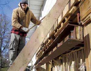
Luckily, the GC took care of removing the asbestos siding from the area where the addition was going; to get started, we just had to pull off the sheathing and remove an existing window and door. Before installing the diagonals, we fastened a temporary 2×10 ledger above the new opening, using 1/2-inch lag screws. We predrilled the studs to prevent splitting, and used plenty of 16d commons as well.
After placing the 2×8 diagonals, we attached a second ledger underneath to prevent them from slipping and to contain the inevitable splits at the notches. We nailed them off at their bases to a plate secured to the floor framing.
Prepping the Opening
The day before we were to install the header, I made a trip to my steel fabricator to double-check measurements and fasten a wood nailer for joist hangers to the web. To be on the safe side, I decided to use pressure-treated material for the nailers in case condensation ever forms on the cold steel.
Meanwhile, back on site, members of the crew cut out the opening in the exterior wall and removed the band joist in preparation for the I-beam. When they were doing this, they noticed that the existing second-story floor joists were 2x8s — not 2x10s as the architect had assumed. That meant the 81/2-inch-deep I-beam wasn’t going to sit flush with the bottom of the existing framing. To gain some additional clearance, we cut away the 5/8-inch subfloor above the header.
A quick phone call to the steel fabricator alerted him just in time that the columns would need to be 5/8 inch longer than the original measurement.
Even with the subfloor cut out, the beam was not going to disappear into the framing. Still, it was close enough that adding strapping to the existing kitchen ceiling would allow us to create the flush ceiling the architect had planned.