Many of the old wood-frame buildings in my region were
originally built on full-basement masonry foundations with
masonry piers supporting the first-floor carriage beam at
midspan.
It may seem that a brick pier makes an ideal choice for this
task, especially when compared with a decay-prone wood post.
But over time, many of these piers have deteriorated in
response to the effects of rising damp, which is the movement
of ground moisture up through the concrete footing into the
brick. Once that happens, salts in the mortar — typically
calcium sulphate — can dissolve, leaving a crystal
deposit in the pores of the brick. Gradually, the crystals
accumulate enough that the pressure inside the pores shatters
the brick. Efflorescence — that white powdery calcium
dust that appears on the surface of masonry exposed to moisture
— is a clear indication of rising damp.
I'm occasionally called on to replace these piers. We often
find light-duty adjustable steel columns installed under the
beam as a stopgap measure against settling. These columns are
not meant for permanent application, and they're not usually
placed on a structural footing. So we install concrete-filled
Lally columns on top of new poured footings.
I don't like to jack up old wooden beams that have sagged over
time. The wood fibers have usually taken a set, making the beam
impossible to straighten, if it was ever straight to begin
with. Jacking would just crack the beam and the plaster in the
rooms above. Instead, we install our steel replacement posts so
as to transfer the load without any need to lift the floor
system in the process. But simply wedging the plate and post up
on a new footing and grouting under the plate won't preload the
column, which is critical in avoiding any further settling of
the structure.
On the job shown here, we replaced the masonry piers with 3
1/2-inch-diameter Lally columns, as specified by the engineer.
Lally columns are typically sold with 4-inch-square
stamped-steel base and top plates. Raised lugs help center the
plates on the column, but they are only about 1/8 inch high and
don't do much to restrain the column against incidental
vibration and movement. So we used "Springfield plates," which
are 6-inch-by-8-inch-by-5/16-inch-thick steel plates with a
1-inch-high welded collar to accommodate 3 1/2- and
4-inch-diameter columns. We had these welded to
9-inch-by-9-inch-by-1/2-inch-thick steel plates, with precise
1/2-inch holes drilled at the four corners for anchoring to the
footings.
We broke through the old concrete slab and dug holes for
24-inch-by-24-inch-by-12-inch-deep footings. When we poured the
footings, we added crossing layers of three #5 rebar for
reinforcement, but poured only 7 inches of concrete to begin
with.
After the concrete set up (about 48 hours), we temporarily
shimmed the base plates level on top of the footings so they
would lie flush with the floor slab [1]. Next,
we lag-bolted the top plates to the underside of the carriage
beam, centered plumb above each footing [2].
We used steel washers to shim the plate level on the rough beam
surface. Because of the dips in the beam and the general
irregularity of the basement slab, each column had to be cut to
a different height. To measure, we used two pieces of strapping
held together with a couple of C-clamps and slid apart
lengthwise to gauge the distance between each top and bottom
plate. This method is easy and more accurate than a tape
measure, and can be transferred directly to the column to mark
the cut.
1
2
Lally columns are easy to cut in the field with a
large-diameter cutter and a pipe vise [3]. The
concrete column core breaks off rough, so we use a 41/2-inch
grinder with a diamond blade to smooth the ends.
3
While each column was still held in the vise, we clamped a pair
of 36-inch-long 2x4 crossties to it, about 12 inches up from
the bottom. I like to make the clamps with Dayton threaded rod,
which is used to connect concrete forms. It has a coarse thread
that allows the nuts to spin with ease and without
cross-threading. To either side of each footing, we stacked 6x6
cribbing to support the crossties and hold the column upright
in place, with the top captured in the Springfield plate
[4].
4
For both anchoring and adjusting the base plate, we ran
7-inch-long 1/2-inch-diameter carriage bolts through each hole,
with the heads facing down, like legs, resting on 3/4-inch
washers to help spread the temporary load. With each head
centered on the washer, like a pivot bearing, we could
precisely position the plate above the slab without deflection
from irregularities in the concrete [5].
5
We fit the base plate under the column and snugged it up
hand-tight. (I mentioned earlier that I'd had precise, 1/2-inch
holes drilled through the plates. If the holes had been made
larger, the legs would tend to heel over and cause problems
with adjustment.)
6
At this point, we could have used the bolts to load the
columns, but that's a slow process. Instead, we used a 10-ton
hydraulic pancake jack under the base plate
[6]. The ram part of the jack is only a couple
of inches high and has a 15/8-inch throw. We checked the column
for plumb and slowly applied jacking force. A temporary
adjustable post shore placed immediately next to the footing
under the beam (and nailed at the top to prevent accidental
spills) provided a simple means of monitoring the load
transfer. As soon as I felt some slack in the shoring post, I
knew the permanent column was preloaded. At that point, all we
had left to do was tighten up the bottom nuts under the base
plate, place top nuts on the bolts, and release and remove the
jack.
7
To finish off the footings, we poured the balance of the
concrete within 3/4 inch of the base plate
[7]. Once the concrete set, we dry-packed
mortar under the plate. In all, we installed 12 posts on this
job without cracking any plaster.
Mike DeBlasiois a masonry contractor in Littleton,
Mass.
Roof Demo by Crane
by Mark
Parlee
Last year, my company was hired to frame a large addition on
a ranch. Most of the building was to remain, but at one end we
had to demolish the roof and walls without damaging the floor
system below. Tearing down the roof in place would have been
slow and dangerous, so instead we brought in a crane to lift it
off in sections.


In preparation, we gutted the interior, cut the trusses free
from the walls, and broke the gable roof into three sections by
slicing through the sheathing and truss braces. Next, we cut
four holes through each section of roof and tacked LVLs to the
bottom of the trusses. When the crane arrived, we dropped cable
through the holes in the first section of roof, wrapped them
around the LVLs, and used shackles to connect them to the
lifting straps. After the crane operator lifted that section
and placed it on the ground about 50 feet away, we repeated the
same steps with the other two sections. Since the crane was
there anyway, we also used it to lift some of the exterior
walls. The $900 it cost to bring in the big machine was well
worth it: Dismantling the roof on the ground turned out to be
safe and quick.
Mark Parleeis a general contractor in Des Moines,
Iowa.
Working Wireless
by David
Grubb
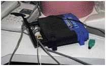
There are two routers on my current remodeling job: One
spins carbide bits and the other pro-vides a WiFi network so I
can connect wirelessly to the Internet. The latter came about
because the clients used a wireless router to access their
broadband connection, and when they moved out they said we
could use it.
Wireless is great on a remodeling job, because setting up a
permanent site office is rarely practical. As soon as you set
up in one room, you get chased out when the crew and subs need
to work there.
With the wireless network, I can take my laptop anywhere in the
building to do e-mail or access the Internet. In the past, this
stuff had to wait until I could get back to my office —
usually at the end of the day. Now, when I have questions for
the owner, architect, or engineer, I can send e-mail messages
straight from the job. I still use my cellphone, of course, but
I actually prefer e-mail because it leaves a paper trail for
documenting decisions.
The architect on this particular job has been e-mailing
drawings as PDF files, a format that just about any computer
can read. He'll send a section drawing for a television
cabinet, for instance, and I'll forward it to the cabinetmaker
and the audio installer at the same time. It's easier and more
reliable than sending a fax.
I use a digital camera to document the job, and there are times
I want to access those photos on site. In the past, they'd sit
on my office computer because there was no point bringing a
laptop to the job when I couldn't connect to anything. These
days, if we run into an unexpected condition, I can immediately
e-mail a photo to the architect or engineer, and there's a good
chance I'll get an answer the same day.
Most of my clients have broadband access, but if the next one
doesn't have a wireless router, I'll bring my own. The routers
cost less than $100, and unless your computer is really old,
the connection is easy to set up.
David Grubbis a remodeler in Berkeley,
Calif.