Download PDF version (839.5k) Log In or Register to view the full article as a PDF document.

Image

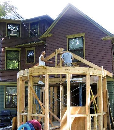
Excited to see an unexpected set of plans in the mail, I ignored the accompanying cover letter and took a quick look. The plans showed a nearly round addition to an elegant 1888 Victorian that would enclose a new window-filled dining area. They also called for a gut and remodel of the kitchen and adjoining bath downstairs, and a new master bathroom upstairs.

After reading the accompanying project documents more carefully, I realized that there were a lot of details that would make bidding difficult — but my main concern was the dining room. Could we build it without losing our shirts in the process? Eager to get this interesting project, my partner and lead carpenter Danny DoCouto pointed out that the room was essentially a regular 16-sided polygon. While the angles would slow us down a little, the actual construction — he assured me — wouldn’t be all that different from the more typical rectangular additions we usually build.

Foundation Layout

Normally we would build the foundation on a project like this. But the adjoining part of the old house had so many problems — including undersized girders and rotten joists and posts — that needed to be addressed during the renovation, we decided to sub out the new foundation. That way we could repair the existing structure while the masonry work was being done and be on site to oversee the layout of the foundation.

The total width of the addition measured 15 feet from sill to sill, with the polygon overlapping the existing house at the sill plate by 6 inches. This put the center point of the addition 7 feet away from the outside edge of the existing sill, and the outer edge of the new polygon foundation 14 feet 6 inches away (see Figure 1).

Image

Figure 1. Dividing the 360 degrees of a circle by the number of sides in a regular polygon gives you the apex angle (here, 22.5 degrees) of the isosceles triangles that can be drawn around the center. Bisecting this angle gives a right triangle that can be used to solve for the lengths of the sides (x) with either a Construction Master calculator or trig function (for example, tan 11.25 = opposite/adjacent). The answer? x = 2 feet 11 13/16 inches.

A 16-sided polygon can be divided into 16 equal isosceles triangles, each with a central angle of 22.5 degrees (360 divided by 16). Using this angle and the 7-foot 6-inch distance from the center of the addition to the midpoint of each side, we calculated the length of the sides.

Before digging the hole, we opened up the side of the house to benchmark the height of the existing foundation and floor framing and to locate the center of the new 10-foot 6-inch opening that would connect the house to the addition. With those dimensions for reference, we outlined the rough perimeter of the foundation with spray paint, then used a rented mini-excavator to dig a hole that would put the bottom of the 12-inch-thick footing more than 36 inches below grade — below frost depth for our part of New Jersey.

Trench footing. I suggested that, instead of building the angled footing form shown on the plans, the masons pour a much simpler 2-foot-wide circular trench footing — a change I ran by the building inspector. From the center of the opening, we strung a perpendicular line off the house, then measured 7 feet out from the sill and drove a form pin into the ground directly underneath this point (Figure 2). From that center pin, we swung 6-foot and 8-foot arcs representing the inside and outside of the footing trench.

Image
Image

Figure 2. The addition’s block foundation was built on a circular trench footing, laid out from the center point of the 16-sided polygon (left). The 12-inch-deep by 2-foot-wide footing was dug by hand in the bottom of the excavation and reinforced with rebar (right).

Because the 16-sided room isn’t freestanding, the footing layout had to deviate from its circular shape as it approached the house, creating more of a horseshoe shape. The masonry crew hand-dug the 12-inch-deep footing trench, laid up the rebar on chairs, and poured the footing.

To lay out the block wall, we made a plywood template designed to pivot on the center pin and used it to mark the sides of the wall on top of the footings (Figure 3). Starting at the outermost wall segment, we moved the template left and then right, marking 11 segments on the footing. We turned the next wall section on each side to intersect the house at 90 degrees, as indicated in the illustration.

Image

Figure 3. To lay out the foundation, the author cut a plywood template based on the dimensions of one of the isosceles triangles that make up the 16-sided polygon. The template registers against the form pin at the center of the addition; the end of the template represents each 2-foot 11 13/16-inch side of the polygon.

Block foundation. Because of all the angles, it made more sense to stack the block than to use a running course. To strengthen the wall, the mason used Durawall galvanized mesh to overlap each joint and poured the cores, adding vertical rebar on each side of the angles. To help the mason check his work while laying up blocks, Danny mocked up a sill out of a pair of 2x4s cut at 11.25 degrees and joined together (Figure 4).

Image

Figure 4. The stacked blockwork was reinforced with galvanized wire mesh on each course. A mock 2x4 sill cut to the exact angle and dimensions of two wall sections helped the masons get the corners right as they laid up block.

While virtually every other block needed to be cut to fit, the foundation was only five courses high, so it didn’t take long to build. Once the masons finished parging and dampproofing, they laid a vapor barrier and reinforcing mesh on the inside and poured a 4-inch-thick rat slab. Before backfilling, we also installed a 4-inch-diameter perforated footing drain protected by a fabric sock.

Floor Framing

By the time we were ready to bolt down the PT sill and get started on the framing, we had completed most of the structural repairs to the existing house. Floor framing was straightforward — except for having to cut 11.25-degree bevels on both ends of 15 pieces of sill and rim joist, and bevel seven of the 11 2x12 floor joists (Figure 5).

Image

Figure 5. The rim joist was cut from 2x10 stock to match the elevation of the existing floor, but the floor joists had to be cut from 2x12 stock for the longest spans of the polygon.

We used 2x12 joists to ensure that we ended up with a stiff floor, notching the bottoms at each end to match the 2x10 rim joists. (Code allows notching at the ends of joists — up to a fourth the width of the member, or 2 13/16-inch in a 2x12). We also installed bridging down the centerline, then sheathed the floor with 3/4-inch T&G plywood.

Wall Framing

To lay out the walls, we had to take into account the widths and angles of the polygon sections, the required rough openings for the windows, and the frieze board running around the perimeter of the existing house. We began by cutting pairs of 2-foot 11 13/16-inch-long plates for each wall section and laying them out around the perimeter of the deck. To tie the wall sections together, we cut the double top plates so they overlapped the bisected angles where the plates met (Figure 6). To further strengthen the wall, we ripped angled 2-by fillers to fit into the triangular-shaped voids between the outside edges of adjoining studs.

Image
Image

Image

Figure 6. With rough-opening sizes that left no room for trimmers, each window wall section was a simple frame consisting of 2x6 bottom and top plates and 8-foot studs (top left). A 2-by ripping fills in the triangular gap between adjacent studs at each corner (top right). An overlapping double top plate helps hold the wall sections together, while roof loads are supported by a box header installed on top of the plates (bottom).

There was enough room in each wall section to accommodate a window rough opening, but not enough for a pair of trimmers to support a header. Instead, we carried the roof loads with a continuous box header installed above the double top plate — a pair of 2x8s nailed together with lumber spacers, with a 2x6 plate across the top. The home’s existing windows tuck in under a frieze board, a detail we matched on the addition. This put the top of the rough openings at about 8 feet.

Completing the polygon. On the exterior, the 16-sided polygon is interrupted where the outside walls return to the house. But on the interior, the polygon shape is continuous at ceiling level, so we needed to extend the wall plates and box header so they wrapped completely around the room. To do this, we completed the full 16-sided polygon layout on the deck and transferred this layout up to the top plate (Figure 7). Then we continued the plate construction around the room, butting it into the new LVL beam we had installed above the opening into the addition.

Image

Figure 7. The interior walls at ceiling level continue the 16-sided form of the polygon, so the wall plates and box header needed to be extended to meet up with the existing wall.

Roof Framing

We planned the roof framing so that half of the rafters — the hips — bear at the top on a “boss,” or finial. This avoided the headache of having 32 roof rafters all meet at a single point. The other 16 rafters bear on a ring of blocking installed between these rafters about 24 inches from the peak of the roof. The boss is a stack of seven 16-sided polygon blocks cut from 2x8 stock and glued and nailed together. We used a temporary post at the center of the room to support the boss at the proper elevation while we installed the rafters (Figure 8).

Image
Image

Image

Figure 8. The 16 2x8 hip rafters were cut and installed first and bear on a 16-sided boss cut from 2x8 stock (top left). Blocking installed between the hip rafters (top right) supports the other 16 common rafters, which bisect each wall section. The rafter tails, fascia, and window trim all had to match the existing frieze detail (bottom).

Danny installed the hips first, then blocked between them to catch the tops of the commons. We dropped this ring of blocking far enough from the peak so that we could reach in easily with a framing nailer. Normally you might drop a hip to match the roof plane of the common rafters; in this case we had to tweak the seat cut of the commons slightly to bring their tops in plane with the unbeveled hip rafters. We sheathed the roof with 5/8-inch plywood, then added a simple cricket where the new roof meets the existing wall.

Typically, continuous ceiling joists or rafter ties prevent roof loads from causing the walls to spread, but the plans for this room featured a prefabricated 6-foot- diameter by 14-inch-deep fiberglass dome (imperialproductions.com, 800/399-7585) right in the center of the ceiling, which complicated the ceiling framing. We first installed a pair of doubled 2x8 headers 6 feet on-center, spanning the room parallel to the existing house (Figure 9). Fastened to the box beam with toenails and metal angle connectors, these joists help tie the opposing walls together and provide the framework for the ceiling grid.

Image

Figure 9. A beefy 2x8 grid ceiling reinforced with metal connectors helps tie the walls together while accommodating an opening for a prefabricated dome in the ceiling center. Before the dome was installed, an insulation contractor sprayed the unvented attic space with closed-cell foam insulation.

To square up the opening for the dome, we hung another pair of doubled 2x8 joists 6 feet on-center between the first pair, then hung the other ceiling joists off these girders on 16-inch centers, using metal hangers and connectors wherever possible to reinforce the grid. Finally, we installed angled 2x6 blocking at the corners of the opening to turn the square into an octagon.

Still concerned about lateral thrust, we also installed two pairs of collar ties perpendicular to each other and high enough above the box header to provide clearance for the 14-inch-deep dome. Securely nailed to opposing pairs of hip rafters, these 2x8 collar ties support a vertical post under the boss, creating a sort of king post under the peak.

After we framed up the grid, the insulation contractor filled the rafter bays with closed-cell polyurethane spray foam, both insulating and air-sealing the unvented roof.

Image
Image

Image
Image

Figure 10. Each of the subtrades working on the project — from the roofer installing the soldered copper finial (top left) to the flooring contractor installing the inlaid linoleum floor (top right) — had to take into account the angles and proportions of the addition’s 16-sided layout (bottom photos).

Cost

It’s hard to estimate how much more this polygon cost to build per square foot than a similarly sized rectangular addition. There’s no question that the room’s angles slowed us down and added to labor costs. But the shape of the room also dictated a number of finishes that probably wouldn’t have been used in a more conventional structure, including a copper finial on the roof (a compromise from the copper roof originally spec’d), granite sills, and an inlaid linoleum floor (Figure 10). In the end, we didn’t lose our shirts, and we learned a little math along the way.

Rob Corbo is a building contractor in Elizabeth, N.J.