Our company builds a dozen or more houses a year. With a crew
of only four carpenters, we can't afford to waste time, so
we're always looking for systematic ways to approach the
work.
In this article I'll describe our method for laying out and
framing a first-floor deck. The techniques we've developed
allow us to work quickly and accurately, and ensure that the
rest of the framing goes well.
Getting Started
We typically split into two teams of two carpenters. One team
rolls out tools and gets the floor framing material ready while
the other lays out the sills. The goal is for the sill layout
to be dead square and perfectly parallel.
Framing errors and compromises tend to accumulate and show up
in the roof; if the sills aren't square and parallel, the walls
will follow, making the roof harder to frame. The error might
even be visible when the job is done.
Longest wall. The first thing we do is snap a line along the
top of the longest wall, 5 5/8 inches in from the outside face.
This line represents the inside edge of the sill; its outside
edge should be flush with the face of the wall. Sill stock is
always a little bit wide, which is why we offset the line 5 5/8
inches rather than 5 1/2.
On a straight foundation wall, the sheathing usually ends up
1/2 inch beyond the face. If the foundation bows out in the
middle more than 1/2 inch, we'll shift the line out until there
is no place where the sheathing will not be at least flush to
the face of the wall. This may change the size of the house
slightly, but that's better than having the foundation touch
the back of the siding.
Creating a Square Layout
Next, we snap a line square to the first line along the top of
the longest intersecting 90-degree wall (see Figure 1).
Figure 1. Crew members snap sill layout
on the longest wall of the foundation (A), mark the inside
corner, and align the laser over that point (B). Next, they
place a target over the line at the far end of the wall and
rotate the laser until the front beam hits the target dead
center (C). Finally, they locate the perpendicular line by
placing the target on the adjoining wall so that the side beam
hits it dead center (D), mark that location, and measure in one
inch to account for the offset between the down beam and side
beam on the PLS5 laser. A line between this point to the inside
corner will be square to the original line (E).
In the past we located this line using the 3-4-5 method or by
calculating the length of the hypotenuse between the far ends
of these walls. Now we use a PLS5 laser (Pacific Laser Systems,
800/601-4500, www.plslaser.com), which projects reference
lines that are perfectly straight and square. It's faster than
drawing right triangles and there's no need to worry about
inaccuracies caused by a sagging tape.
Using the laser, we can create square layout on a large
foundation in a matter of minutes.
Aligning the beam. We begin by making a mark 5 5/8 inches in
from the end of the line we made on the longest wall. This
represents the inside corner where two sills will meet.
Next, we place the laser on the wall, align the downward beam
with the corner mark, and aim the main horizontal beam toward
the far end of the wall.
Our goal is to position the horizontal beam directly over the
line on the wall. To do this, we position the laser target on
the far end of the wall so that the pointer lands on the line.
Then we rotate the laser so it projects a dot on the centerline
of the target.
On a long wall, adjusting the laser takes very little movement;
for fine adjustments, we tap lightly on the side of the laser.
When the beam hits the target's centerline, we know it's
aligned with the chalk line.
Projecting a perpendicular line. The next step is to project a
second line at a perfect 90-degree angle to the first and mark
it on the adjoining wall.
The PLS5 projects three horizontal beams, two of which are
perpendicular to the main horizontal beam. The main beam is
already aligned with the line on the foundation, so to create a
square layout we just have to determine where the side beam
passes over the intersecting wall.
We do this by taking the target to the far end of the
intersecting wall and positioning it so that the side beam hits
it dead center. Then we mark where the pointer lands on the
concrete.
With the PLS5, the side beams project at a one-inch offset from
the vertical beam (in this case, one inch too close to the
outer face of the wall), so we measure over an inch and use the
new mark to snap a line back to the corner where the two sills
will meet.
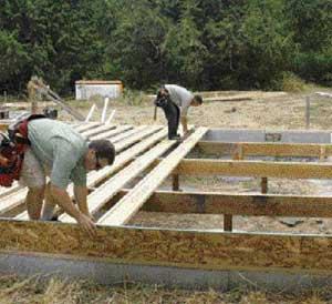
Laying Out the Remaining
Walls
Now that we have two lines that are perfectly square to each
other, laying out the rest of the walls is simply a matter of
measuring off the first two lines. Difficulties arise only in
places where the foundation walls step up and down or where we
need to drop our layout onto a basement floor slab.
The traditional way to handle these areas is to stretch a tape
horizontally and then use a plumb bob or level to carry the
layout down. We find it faster and easier to stretch the tape
and use the laser's up and down beams (the plumb beams) to
carry the layout down (Figure 2).
Figure 2. To lay out sills on a stepped
foundation, most carpenters stretch the tape horizontally and
use a level to plumb down (left). A faster method is to stretch
the tape, position the laser so the up beam hits the desired
mark (above), then mark where the down beam hits the
foundation.
Installing Mudsills
Once layout is snapped, we gang up on the mudsill. If the sill
is to be attached with anchor bolts, three framers mark bolt
locations while one carpenter drills holes.
Anchor bolts. To locate the holes, we place the sill against
the bolts, align a square with a bolt, and scribe a line across
the sill at that location. We then measure the distance between
the layout line (on the foundation) and the center of the bolt
and make a mark that far in from the edge of the sill on the
line we just scribed (Figure 3). The mark will be the center of
our hole. It's important to do this accurately because the hole
should not be greatly oversized.
Figure 3. A carpenter butts sill stock to
the bolts, squares in from them (top), then measures the
distance between each bolt and the layout line (bottom left).
After marking that distance on the stock, he drills the bolt
holes (bottom right).
We have tried using a specialized marking tool, the Bolt-Hole
Marker (Big Foot Tools, 702/565-9954,
www.bigfoottools.com),
but found it difficult to balance a 2x6 plate on the stem wall
while making the marks. This tool is much better suited for
marking plates for slab foundations.
Once we're about halfway through marking and drilling, one
framer breaks off from marking and begins to fasten the sills
with nuts and washers. We tighten the nuts with an electric
impact wrench, taking care not to overtighten them.
Straps are faster. Not long ago, we stopped using anchor bolts
and started using a type of cast-in strap that wraps over the
sill and is fastened to it with nails. We happen to use
Simpson's MA6 anchors, but USP makes something similar, the
ST1-TZ.
On our crew, one carpenter cuts and places sill stock on the
foundation, a second follows behind and tacks the sill on
layout with a powder-actuated tool, and a third makes the
structural connection by bending the straps over the sill and
fastening them with a metal connector nailer. We tack down the
sills to prevent them from moving while the straps are being
nailed (Figure 4).
Figure 4. Fastening sills with cast-in strap anchors (top left)
is faster than using anchor bolts. The carpenters place the
sill stock on layout, tack it in place with a powder-actuated
fastener (bottom left), then fasten it by nailing on the strap
(bottom right).
Using straps is much faster than using anchor bolts because
there is no need to lay out and drill holes. Another advantage
to using straps is that we never have to move a joist off
layout because a bolt is in the way; since straps are thin, you
can run joists and rim boards right over them.
To avoid having to use galvanized or stainless steel fasteners,
we use borate-treated lumber for the sills (see "Fasteners for
ACQ Plates," Q&A, 1/06). We frame quickly so that the sills
are not exposed to the weather long enough for the borate to
leach out.
Using Girders to Break Up
Spans
Most of the homes in our area are built over crawlspaces, so we
install rows of girders 8 or 9 feet apart to break up long
floor spans and pick up point loads. This makes for a stiffer
floor and eliminates the need for a stem wall at the center of
the house.
We don't do this with basements, however, because that would
require too many posts. Instead, we use larger joists, and
— when necessary — break up the spans with bearing
walls.
The tops of the girders should be flush to the tops of the
sills. On large houses we install the sills that are
perpendicular to girders first; that way, part of the crew can
set girders while the rest of the sills are being
installed.
We start by scattering the girder stock so we can cut the
pieces where they go. The ends of the girders will be supported
by posts that land on ribbon footings (long thin footings) or
footing pads (Figure 5).
Figure 5. With a crawlspace foundation,
the author uses girders to break up the floor span. Instead of
measuring, the crew lays the girder stock in rough position
(top) and cuts the pieces so the joints land over footing pads
(bottom left). The girders are supported by posts that land on
pieces of rubber membrane and are tied to the footings with
cast-in straps (bottom right).
The footing pads vary in elevation, so each post has to be cut
to a slightly different length to keep the girder level. To
quickly measure post length, we stretch a string very tightly
from sill to sill where each run of girders will be, measure up
to it from the footing, and deduct the height of the
girder.
If the run is more than 25 feet long, we add 3/16 inch to the
height of the center posts to account for the sag in the
string.
We have used a rotary laser to determine the height of posts,
but that approach is slower than using a string. The laser is
more accurate, but our primary objective is for the tops of the
girders to be in a straight line between the sills. We don't
care if a run of girders is slightly out of level — say,
within 1/4 inch from end to end. (If the stem walls are off by
more than that, we shim the mudsills.)
We cut the posts, stand them over a piece of PVC membrane, and
install girders on top. The posts are fastened to the footings
with cast-in straps and to the girders with nailed 2x4 gussets.
We sight the girders before nailing them off; if there is
excessive crown, we'll cut the girder over an intermediate
post.
The girders normally stop short of the stem walls, so it
doesn't matter that they aren't treated. If the ends are less
than an inch from the concrete, we cover them with PVC
membrane.
Laying Out and Installing
Joists
Once the girders have been installed, we clean out the
crawlspace and lay out the locations of joists and beams on the
sills and girders. To minimize errors, only one carpenter does
layout; the rest of the crew scatters the joists and sets
beams.
I-joists. We use I-joists about half the time. Our supplier
provides a "precut" package based on the plans, so we have to
pay close attention to the lengths the manufacturer sends. The
joists come several inches long and we trim them on site.
We like to scatter the longest joists first, just to get them
out of the way. While one framer installs rim, another uses a
forklift to boom the joists over the foundation so that the
other two guys can unload them (Figure 6). With the forklift,
it takes only about 30 minutes to scatter all the joists for a
1,500-square-foot floor.
Figure 6. After the girders are in, the
crew installs rim boards (top), then places the joists in rough
position (bottom).
If the joists are less than 25 feet long, our preferred method
is to use a chain saw to cut them while they're still banded
together; if they're longer than that, they'll bend too much
and throw off the measurement.
When the joists are more than 25 feet long, we leave off one of
the rims, butt them to the opposite rim, snap a line for the
cut, and cut them in place with a circular saw (Figure 7). We
then install the last of the rim and begin to roll and fasten
the joists.
Figure 7. Rather than measuring each
joist, a carpenter butts them all to the opposite rim, snaps a
line where the inner face of the rim will be (left), and then
cuts them in place with a circular saw (right).
Nailing. We follow the I-joist manufacturer's recommendation
for nailing. We use RFPI Joists (Roseburg Forest Products,
800/347-7260,
www.rfpco.com), which
require one 8-penny nail through the rim into each flange and
two 8-penny nails through the bottom flange (one on each side)
into the rim (Figure 8). With solid-sawn joists, we use
10-penny nails to fasten every 1 1/2 inches through the rim
into the joists as well as to toenail the joists to the
sill.
Figure 8. To finish the frame, the author
nails joists to the rim (top left) and sill (top right), then
installs the required blocking (above).
If we're using I-joists, the manufacturer supplies precut
I-joist blocking, or LVL blocking when the engineer says it's
necessary. With solid-sawn joists, we use solid lumber
blocking.
Sometimes we're required to install double blocking under shear
walls, in which case we make the blocks out of cutoffs from the
4-by girder material.
Figure 9. When installing the subfloor,
everyone has a particular job: One carpenter does nothing but
glue, two carpenters cut and place the sheets and beat them
together, and one just nails.
Inspection
The building inspector needs to inspect the frame before we
install subflooring. Framing the floor normally takes us five
or six hours, so we schedule an inspection for the afternoon,
and unless there are major problems we can sheathe the floor as
soon as he leaves.
If the inspector asks for anything, it's usually that we add a
few more pieces of framing hardware to tie the rim to the sill
or that we add some extra anchor bolts to the foundation. When
we need to add anchor bolts, we use 1/2-inch Kwik Bolts (Hilti,
800/879-8000, www.hilti.com), a type of wedge
anchor.
If at all possible, we sheathe the floor and snap out the walls
on the same day. That way, we can start framing the walls first
thing the next morning. If we aren't finished when the
inspector comes out, we have to call in for another inspection
and we lose the next day on the job.
Laying the Floor Sheathing
When we install subflooring, everyone sticks to a particular
task until the floor is done. Since there are four of us, the
first carpenter applies the glue, and a second packs material
and beats the sheets together so that the T&G joints will
close (Figure 9). A third packs material and cuts, and a fourth
does nothing but nail.
We trade off on every house so that no one has to do the same
thing all the time.
Gluing is the weakest link in the process. Even with a
pneumatic glue gun — which is way faster than operating a
gun by hand — the guy doing the gluing has to hustle to
stay ahead of the rest of the crew.
We're very production-oriented about this; on a recent project
we installed the subfloor on a 3,000-square-foot single-story
home (95 sheets) in a little less than two hours, including
trimming the edges.
During the drier months of the year, we sheathe floors with
LP's midlevel OSB product, TopNotch Orange Plus (888/820-0325,
www.lpcorp.com).
But during the rainy winter months, we'll spend the extra $3 to
$4 per sheet it costs to get AdvanTech (Huber Engineered Woods,
800/933-9220, www.huberwood.com), which is less likely to
swell when it gets wet.
Tim Uhler is a lead framer for Pioneer
Builders in Port Orchard, Wash., and a JLC contributing
editor.