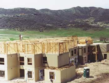
All of the material in the conventionally framed wall system for this ski company housing project was pre-cut and shipped from about 450 miles away. |
Pre-cut, prefabricated, and modular systems all have inherent benefits and drawbacks. My first attempt at prefabrication using an “automated” assembly line setup was a full wall panel on a multifamily project, calculated and drawn by hand. Although this approach was crude, it was surprisingly effective. I created a layout book and began building prefab walls. I took the book home at night and used white-out for minor adjustments, redrawing and pasting in larger corrections. It changed day to day, but by the time the project was in full swing, we had a product that worked very, very well. Prior to that, for about 10 or 15 years, we did everything we could think of in conventional prefab, including arches, drop ceilings, and framed roof details. Everything we did seemed to pay off. Most notable was the amount of waste, which was next to nothing. And as our construction company’s market expanded from New Mexico into places like Aspen and Vail, Colo., where labor is both scarce and expensive, I thought prefabrication would still be the answer to all our clients’ needs. Shipping air. But I eventually discovered the Achilles’ heel of panelized walls — freight costs. You can turn one tractor-trailer load of lumber into six truckloads of walls. Any savings you realize from the efficiency of panelization is eaten up by the cost of shipping. The term in the business is “shipping air.” Somehow I had to use what I had learned about assembly line techniques to achieve a competitive edge.
A System Evolves
My answer to the problem was to do a partial, or hybrid, prefab. I would pre-cut all the walls, lay out the plates, build the components, and ship packages of wall plates and bundles of components to the site for assembly. The advantage of this process is efficiency; speed, accuracy, quality control, no mistakes, no storage problems, and optimal use of labor.
Halfway there
. We realized some of the benefits of factory-style fabrication, but there were drawbacks. The projects that we shipped were fairly complex, with up to fifty different units of components, including headers, trimmers, channels, and corners, all of various sizes. When a crew would break into a unit of pre-cut, pre-laid-out lumber, they would spend half the day roaming a field of stacked components, gathering one of this, four of that, and so on. This was not an efficient way to build. Many of the projects that we contracted for were on small sites, and we simply did not have the room to spread out. A different approach was required.
Freeze-dried walls
. The idea started to gel as I watched a documentary on climbers attempting to scale Mount Everest. I saw them huddled in their tents preparing freeze-dried meals thousands of feet above the nearest stove top. “Why not freeze-dried walls?” I thought. The idea is to bundle a plate, component, hardware, and nail package. Just add a little labor, and you have a panelized building package, miles away from the nearest prefab plant. Of course, the thing about great ideas is that unless you have the right people to execute them, they remain just ideas. Luckily for me, I did have the right people. We are now turning out neat, easy-to-ship “freeze-dried” units — about four or five projects a year — 60,000 to 180,000 square feet each, and assembling them within about a 500-mile radius of our headquarters in Albuquerque, N.M.
Hybrid Prefabrication
My process is not a true prefab operation because we don’t actually assemble the plates and components into finished wall panels. It is actually a pre-cut framing package (see Figure 1), composed of everything required to frame a hotel or apartment unit completely. You may have seen similar packages on piecework frames in California. We have taken that concept a few steps farther. While we developed the system with multifamily projects in mind, it could work equally well for tracts or large custom projects.
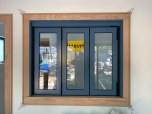
Figure 1. Everything is fitted carefully to keep freight costs down and create a tight, solid, stackable package that will help reduce warping (left). “Hybrid-prefab” packages contain everything you need to build walls, including pre-cut plates, headers, trimmers, channels, corners, nails, hardware, and drawings (right). | null |
On one semi-truck we can typically ship enough pre-cut, labeled, and packaged material to cover a 20,000-square-foot area in walls. Each banded, wrapped, and numbered package measures 4 feet wide and 16 feet long. The height depends on the size and complexity of the unit. Units are designed to fit two abreast, three units end to end, and stacked 8 feet high — about 23,000 pounds. Along with every prenailed subcomponent required (such as sills, cripples, headers, trimmer assemblies, corners, channels, nails, and hardware) our packages include every plate — cut to length and detailed per the plan. Every member is labeled, nailed, drilled, and fitted as required. Every package includes a dimensioned layout and placement plan and a plastic-wrapped shipping list with a printout of exactly what pieces are included. This includes a list of the wall plates, indicating the width and length of each wall, as well as elevations for walls where additional clarity would be helpful. Quality and efficiency. Every step of our process has multiple quality controls built in. Quality is our foremost concern, because the product that we are shipping will be delivered to carpenters who are paid twice as much as our prefab team. Plus, the men in the field are working in far rougher conditions: limited space, snow, cold weather, and so on. Our goal is to take half the work and all the thinking out of framing.
Where To Start
The process starts with a careful review of the plans, which enables us to catch discrepancies early on that might lead to problems in the field. My associate, Christopher Head, who has training in both architecture and framing, inputs data into a commercially available computerized wall-panel design system (Figure 2). He is very methodical, and when he prints out a set of walls, you know they are going to work like a charm.
Figure 2. It all starts with a careful review of the drawings and a Keymark design system. Mistakes are a lot cheaper and easier to correct on paper than during cutting or assembly. |
More from Journal of Light Construction
-
Monopour Lessons Learned
11 MIN READ
-

-
A “Both/And” Treatment for Windows
4 MIN READ