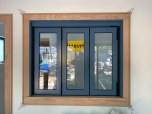
Before
The owners of the 1970s home shown here liked to cook and entertain, but they were continually frustrated by a cramped floor plan. The original kitchen was tucked into a niche at the back of the house and felt cut off from other rooms. When they contacted our design-build remodeling company, the owners had no specific ideas in mind; they just knew they wanted a larger kitchen that connected with the spaces around it and included design features that would draw guests into the room — a “wow” factor, as they called it.
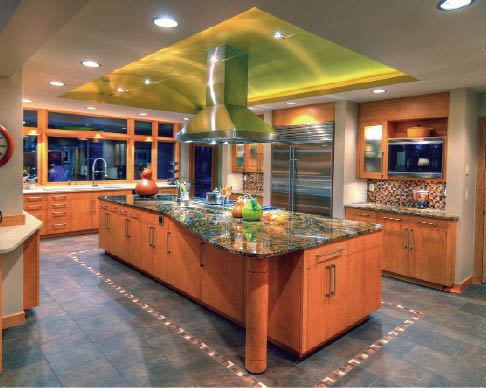
In response, our in-house architect came up with a plan that involved building an addition off the back of the house and relocating the laundry room to another area. The existing kitchen was around 200 square feet; we would be adding another 360 square feet and wanted to do something to make the area special. In many kitchens, the island is the centerpiece of the room, so we decided to create a complementary focal point on the ceiling above. Since we had been in the attic and knew there was space to expand vertically, we suggested building an uplit barrel vault centered over the island. The owners liked the idea because it took what would have been a large, low ceiling and turned it into a conversation piece.
One end of the vault would be in the roof of the addition; that was new construction, so we were confident it would be easy to frame. The tricky part would be framing the section of the vault within the existing footprint, because the roof above was framed with trusses.
We asked the manufacturers supplying trusses for the addition what they would do to create space for a vault within the existing roof. They suggested replacing the existing trusses with new ones that were raised in the middle. We rejected this idea because it would have required that we remove a large area of clay tile roof and demolish the ceilings in adjacent rooms — work that would have added about $25,000 to the cost of the job. It would be less expensive for the clients and less destructive to their home if we could create the necessary space within the existing trusses.
An Engineered Solution
A truss roof is an engineered system, so we knew we’d need an engineered design before cutting or altering these trusses. We hired structural engineer Dan Jordan, who came up with a plan that would allow us to remove a section of the bottom chord from the common trusses above the kitchen, then reframe a cavity large enough for the vault.
The trusses were 64 feet long; they extended from exterior wall to exterior wall, with no bearing points in between. Jordan’s plan added two intermediate bearing points to the truss configuration — one directly above the back wall of the garage and the other at the line between the kitchen and family room, directly under the ridge.
Demolition came first. To avoid having the blown cellulose insulation fall down on us, we hired an insulation company to vacuum out the old insulation using the same equipment they would use to blow it in. We then removed the ceiling drywall and began the structural work.
Our first step was to install an 8×6 tubular steel beam against the bottom of the trusses at the opening between the kitchen and family room. We supported the beam on a pair of 5 1/8-inch glulam posts that ran to the foundation below, bolting it in place. This beam would support one of the new bearing points in the altered trusses; the other support, the garage wall, was already in place.
Altering the Trusses
To avoid damaging the structure, we altered the trusses one at a time, shoring against the top chord with 2×6 braces that ran to the floor. Following the design, we attached 2x8s to the edges of the vertical webs above the new bearing points, fitting them tightly between the angled top chord and the diagonal web at the bottom. We secured the 2x8s to the truss with 1/2-inch plywood gusset plates on both sides, using medium crown staples instead of nails to reduce the risk of splitting.
Next, we shortened the one vertical and two diagonal webs above the vaulted area, creating space for a new 2×10 bottom chord, which we installed 2 feet above the existing bottom chord. Again, we made the attachments with plywood gussets and staples, and also added metal tension straps at each end of the 2x10s, per the engineer’s design.
We were required to run diagonal 2×4 braces between the vertical web at the edge of the kitchen and the bottom chord in the adjacent room. As with the gussets and straps, the engineer specified the type and number of fasteners to be used for these connections.