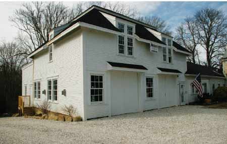
In the fall of 2008, our design-build company took on the job of converting an 1810 barn to living space. The barn was being used for storage and was in rough shape; in fact, other contractors looking at the job advised tearing it down and starting over. But since the building stands in a prominent location in a historic district, the owners feared a public protest and thus a long, contentious approval process for demolition. So instead, we proposed going forward with the job as a repair under an engineer’s supervision — an approach that got us the permit.
By the time we completed the structural revisions, we’d replaced approximately 70 percent of the building, preserving the original roof framing and some of the walls. But because we never actually leveled the barn, the process was relatively quick and we created a lot of good will in the community.
Existing Conditions
On its north side, the 32-foot-by-36-foot barn shares a common wall with the main residence. The roof is a mansard-style double hip with a 12-pitch lower slope and a 6-pitch upper slope. A 6×6 purlin supports the break between slopes. Modifications were made over the years with little apparent regard for the laws of gravity. The rafter plate had been cut to accommodate dormer windows, and collar ties were few and far between. While the attached residence on one side provided some resistance to rafter thrust, the south wall was pushed seriously out of plumb. In places, the dry-laid stone foundation had settled into the clay soil, bringing the framing in contact with the ground. This was causing walls to rot and exacerbating the structure’s wobbly lines.
Clearly the barn had to be jacked up, the foundation replaced, and the framing replaced or restored.
Other than its sag, the roof framing was in good condition, but many of the original balloon studs were rotted near the bottom and would have to be replaced. Because we didn’t completely trust the wall framing to support the roof while we lifted the building, we decided to jack the walls and roof separately. We figured that by taking the weight of the roof off the walls, we could install a new crawlspace foundation, then replace the walls a section at a time with new platform framing. We’d also replace the undersized first- and second-floor joists with new I-joists and AdvanTech subfloors.
Shoring
In the course of our remodeling work, we do a fair amount of house lifting, so we own around $20,000 worth of cribbing and long steel I-beams. Although we shored the roof and walls independently of each other, we did so off the same six stacks of cribbing. We cut through the first floor and set the cribbing on grade in two parallel rows. The rule of thumb when you set cribbing is to lay the bottom course at least 6 inches deeper than any anticipated excavation. It’s common sense; you never want to risk undermining the crib. We were excavating for a minimum 3-foot crawlspace and dug the cribbing in accordingly.
The cribbing supported two primary 60-foot-long steel I-beam “needles” running front to back through the structure. These beams picked up doubled 2×12 cleats that we lag-screwed to the front and back walls, and also supported four 40-foot perpendicular I-beams that in turn picked up 2×12 cleats along the side walls.
To support the roof and provide jacking points, we laid two 20-foot-long I-beams across the needles, directly below the 6×6 purlins that support the break between the lower and upper roof planes. We then built six site-laminated 6×6 posts, running them from the 20-foot I-beams up through the second floor to the purlins. Below the roof, we installed plenty of 2×6 cross-bracing to help the posts act as a unit and prevent bowing.
Jacking
This arrangement allowed us to jack under each I-beam and the needles to gradually restore the building to a relatively level condition. We use ordinary, 20-ton short-throw hydraulic bottle jacks, set on cross blocking inside the cribbing, to make height adjustments. We never lift more than an inch at a time before reshimming and resetting the jack. If a hydraulic seal blows, you don’t want the building suddenly dropping several inches and pancaking on you.
We set a benchmark in the loft at a location along the 8×8 wall top plate where we’d determined the barn had not settled and checked the rest of the plate against it with a laser level as we jacked the walls. Instead of reversing all of the settling (more than 8 inches overall) in one abrupt session, we jacked 1/2 inch at a time, then let the building relax overnight. We knew we couldn’t reverse all of the settling and ultimately settled for a variance of about 2 inches overall from the original elevation.
Jacking the roof could not alone pull the bowing 8×8 plates and leaning walls back in. For this, we cut holes in several locations above and below opposite plates, wrapped chains around the plates, and tensioned them with HIT 3-ton lever hoist come-alongs (purchased through Arizonatools.com for about $400 apiece). To help distribute the force and prevent the chains from biting in, we placed 4-foot lengths of 6×6 on the outside, under the chain, and armored the corners with angle iron. These hoists are capable of pulling the building in on itself if you’re not careful.
As we jacked the roof, we retensioned the chains and the plates moved inward, bringing the walls closer to plumb. We made 1/2-inch corrections each day, taking about a week in all to finish. When the plate sighted reasonably straight and the walls were within a few degrees of plumb overall, we called it good. (Later, when the new walls were in place, we created plumb interior surfaces by stretching gauge lines and adding tapered studs and shims as needed.)
Foundation Replacement
Because of the barn’s historic designation, the exposed stone foundation at the back had to remain intact, even though it was structurally useless. However, most of the shallow foundation along the front and sides had long since vanished into the site’s clay soil, so here we were allowed to pour new grade-beam footings and crawlspace foundation walls. Since the barn was built on a mostly unexcavated slope and we needed to create a 3-feet-deep crawlspace, we first gutted the first-floor framing, then excavated from the interior, working around the cribbing with our mini-excavator and skid steer loader. Where the machines couldn’t go, we shoveled by hand.
To preserve the rustic foundation at the rear of the barn, we poured a 12-inch-thick steel-reinforced footing directly inside the stonework and framed a pressure-treated pony wall on top. After cutting away the old studs for clearance, we extended new floor joists past the pony wall over the top of the stone, for a total overhang of around 18 inches.
Working Around Cribbing
Since the cribbing was critical to the building’s support throughout the repair phase, we had to frame the floors around each stack. We did this by framing and sheathing the deck to either side, then shoring with cribbing beneath the new joists and shimming it snug. Then we continued cribbing up to the underside of the I-beam and shifted the load over onto the relocated stack.
Once we completed the first-floor deck, we installed temporary supports under the joists overhead and replaced most of the two-story balloon studs with new platform framing. Because the roof framing was still supported independently, this was a relatively straightforward swap-out. After the first-story walls were in place, we framed the second-floor I-joist floor system, working around the six posts propping up the roof.
Steel Roof Truss
To support and unify the roof framing, our engineer designed a rugged tube-steel truss that bears on four 4-inch-square steel columns extending up from the concrete foundation. The truss was custom-cut on site and fitted in place under the irregular roof framing. We made plywood patterns to enable the welder to cut the steel accurately. The steel fits snug under the 6×6 collar beams, shouldering the entire load of the roof system and eliminating any need for collar ties. Diagonal bracing within the truss provides the roof with the necessary resistance to wind loads, a real concern in this 110-mph coastal wind zone.
We set the bottom chords of the truss dead-level to a laser line, creating a nice flat ceiling plane. Short lengths of threaded rod tack-welded to the bottom chords hold 2×10 cleats, which we used for face-hanging the 2×10 ceiling joists. A scuttle through the ceiling provides access to the new attic.
Looking at the plumb walls and flat ceilings in the new interior, you’d never know what rough shape this building had been in. And with new roofing, trim, and siding outside, the barn is good for another 100 years.
Fred Ambrose owns Ambrose Homes in Wellfleet, Mass. Ezra Ambrose, his son, manages the job site.