Since its invention nearly 50 years ago, solar electric power has been a reliable but relatively expensive technology. Now, however, the cost to produce electricity from sunlight is coming down. Climbing utility rates, combined with the rebates that some states offer, are making photovoltaic (PV) power systems cost-effective in many parts of the country.
In 1975 I started a company in Northern California that specialized in solar thermal hot-water systems. While we still install those systems, the bulk of our business these days comes from designing and installing PV energy systems for residential, commercial, and municipal clients. Sum total, we’ve installed over a megawatt (one million watts) of solar energy capacity.
In this article, I’ll explain how PV power systems are designed and installed, so that contractors know what to expect when a client decides to buy one.
What Customers Want
Clients have different reasons for wanting to install PV power. For some, it’s a way to act on environmental values or to become self-sufficient. Others look at the rising energy costs and believe that, in the long run, it will be cheaper to produce their own power.
Financial incentives. Many states, local governments, and utilities provide rebates and tax breaks to property owners who purchase PV systems. The state of California currently offers a cash-value rebate of $2.80 for each watt of solar capacity installed. A typical 4,000-watt residential system costs about $8.40 per watt without a rebate. The rebate brings this down to $5.60 per watt. In New Jersey, the rebate is $5.50 per watt. Lower rebates are offered elsewhere; for a database of state incentive programs, go to www.dsireusa.org.
Service life. The systems we install are designed for a 30-year service life. For the customer, it’s like paying up-front for 30 years’ worth of electricity. We can design the system to offset all or part of the client’s electricity needs. Most customers opt to entirely eliminate their utility bills.
Solar modules come with 20- to 25-year warranties stating that the module will still produce 80 percent of its rated output at the end of the warranty period. In fact, the module will continue to function indefinitely, but the output will drop over time. Power inverters typically require one major service or replacement during the life of the system.
Common Misconceptions
Many people are confused about what solar can and can’t do. One misconception is that solar modules must be installed on racks that project way off the roof. Solar modules do perform better when oriented perpendicular to the sun’s path, but they definitely look better when installed flush to the roof. This reduces output, but can be offset by using money that would have gone into the rack to increase the number of modules.
Battery backup. Another misconception involves what happens at night or when the electrical grid is down. There are two types of solar electric systems: grid-tied systems without battery backup, and stand-alone systems that may or may not be tied to the grid but have battery backup. If the utility grid is reliable, we recommend against the added cost and complexity of a battery-backup system. The only time we recommend batteries is when the customer absolutely requires uninterruptible power or is in an area where a grid connection isn’t feasible.
Nonbattery grid-tied systems will not provide power when the grid goes down. For safety reasons, the inverter in a nonbattery grid-tied system automatically shuts down when the grid is out, thus preventing electricity from backfeeding into power lines and injuring linemen who are making repairs.
Net metering. In most states, net metering legislation allows individuals to feed excess solar energy into the grid. The utility meter spins backward when clients are putting electricity in and forward when they are taking it out. In a case like this, where there is no need to store energy, the customer can install a less expensive grid-tie-only system.
Some customers believe the utility will pay them if they put in more power than they take out. Unfortunately, utilities will not pay for unused credit. The best a customer can do is pay nothing for electricity used. As a result, there is no financial incentive to design a system that produces more power than the client needs.
System Components
The most visible components of a standard grid-tied PV system are the solar electric modules; these roof-mounted devices convert sunlight to electricity. The modules produce DC power, which passes through a DC-rated disconnect switch on its way to a power inverter. The inverter converts the DC power to AC and sends it to the main breaker box via an AC-rated disconnect and standard circuit breakers. Battery-backup systems require additional components, including controllers, power centers, solar subpanels, and batteries.
Solar modules. Most people refer to individual solar modules as “panels,” but, technically, a panel is a group of modules that are wired together. The roof-mounted portion of the system is called an array.
Solar modules are produced by a number of manufacturers and come in many sizes and shapes. Right now, our best-selling model is a particularly efficient 185-watt unit from Sharp. It weighs 37 pounds, measures 62 inches by 32 inches, and is 2 inches thick. The edges are framed in aluminum and the face is covered with tempered glass.
Strings. Modules are ganged together on the roof and wired in series. Each group of series-wired modules is called a string, and often there is more than one string per inverter. A typical residential system might contain 21 185-watt modules in three strings of seven.
Most solar modules produce either 12 or 24 volts. Higher voltage does not equate to more power, however, because a 12-volt unit operates at higher amperage than a 24-volt unit of equal wattage. Other things being equal, output is determined by the number and type of modules. The modules usually account for 75 percent of the total cost of a PV system.
Installation Environment
The installation site will dictate the overall size of the system. Considerations include roof orientation, shading, available roof space, aesthetic concerns, and the capacity of the existing service panel.
Life span of roof. Solar modules usually have to be removed to reroof a building. Fortunately, the 30-year design life of a solar energy system is similar to the service life of most roofing products. It makes sense to synchronize reroofing with the installation of PV modules. We recommend reroofing the building if there are obvious signs of wear and tear or if the roof has less than six years of service left.
Location. It’s extremely important to avoid placing modules where they could be shaded by trees, power lines, and other obstructions. Ideally, modules would face due south. In some cases, though, it’s possible to install them facing slightly east or west; the drop-off in production is not always that great.
In this area, an array could be oriented to the southwest and still produce 90 percent of what it would produce if it faced due south. An easterly orientation would be a poor choice because we get a lot of morning fog.
Mounting Schemes
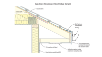
Solar modules can be installed on nearly any type and pitch of roof. They are usually attached to racks — metal rails supported a few inches above the roof’s surface by mounts that are bolted to the rafters.
New construction and reroofs. It’s easiest to install mounts on new construction or on a roof that has been stripped; this way, we can fasten them without having to worry about leaks. On these jobs, we put post mounts on the sheathing and lag them to the rafters. We then flash the posts with the same flashings used on plumbing vents. This obviously produces more penetrations than usual, but the roofer should be able to warranty his work, because everything is properly flashed.
Tile. On tile roofs, we use an aluminum mounting channel called a Tile Trac (Professional Solar Products, 800/847-6527, www.prosolar.com). The channel bolts to the deck and a threaded post extends up and passes through a 3/8-inch hole in one of the tiles. This penetration is caulked and, because it’s high on the tile and covered by a module, it doesn’t leak.
Existing roofs. Retrofits are trickier. On tile roofs, tiles must be removed and reinstalled over the mounts. On flat roofs, some of the membrane must be removed and patched back in.
We install many systems over existing composition shingle roofs. The preferred method is to fasten mounts through the shingles. Tile Trac works well for this application. It comes in 8-inch sections, which we install up the slope on a thick bed of sealant. We’ve put a lot of effort into finding appropriate products for this application and have settled on tripolymer sealants like Geocel 2300 (Geocel Corp., 800/348-7615, www.geocelusa.com) because they are durable, adhere well, and are compatible with asphalt shingles. As an added precaution, we divert water from the penetration by installing a piece of step flashing just upslope.
On retrofits, it’s important to avoid drilling unnecessary holes through the roof. It’s easy to locate rafters when the tails are exposed, but when they aren’t, we go into the attic and drill a pilot hole next to the rafter where the first mount will be located. We leave the bit sticking up and locate other mounts by measuring off it. Rafters may not be evenly spaced, so we always check the layout from inside.
Loads. The local building department will want to know how much load the solar array adds to the roof. It’s typically 4 pounds per square foot. We’ve had some success convincing concerned inspectors and engineers that the added load on the existing structure is okay because no one can walk on an area that’s covered with modules. Also, it doesn’t snow in our part of the country, so offsetting the local requirement for 20 pounds of live load with 4 pounds of dead load is usually a no-brainer.
Hardware. Our systems are designed to last 30 years, so it’s important to use hardware that will not corrode or react. All of the components on the roof are made from aluminum or stainless steel, including the lags that secure mounts to the roof, and the nuts, bolts, and washers that hold the other parts together. We’ve come across corrosion problems that occurred when competitors combined aluminum, copper, and galvanized steel in the same installation.
Wiring
Whenever possible, we rough in home-run wiring from the roof to the inverter location while the studs are still open. On retrofits, we typically penetrate the roof eaves and run conduit down the outside of the building. We always make sure that the owner signs off on the location of the conduit.
Once the conduit is installed, the solar crew pulls home-run wiring from the module locations to the DC disconnect. Typically, it’s 10-gauge or 12-gauge outdoor-rated stranded wire.
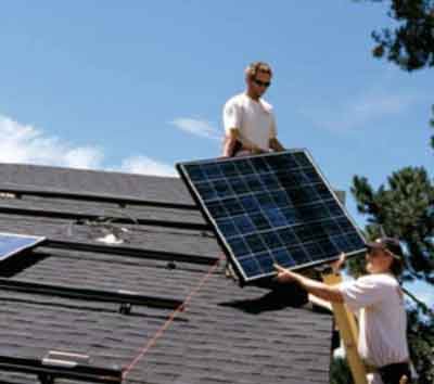
Connecting the modules. We fasten the modules side by side on the rack and wire them together in series. Each module has a positive and negative wire: The positive from one module connects to the negative on its neighbor. We used to hard-wire between connection boxes on the backs of modules; now we connect them using wires equipped with a waterproof quick-connect device.
Grounding. Grounding is extremely important and is something every inspector is familiar with. Section 690 of the NEC (which deals specifically with solar power) requires all modules and metal racks to be bonded to the house grounding system. It also requires a ground-fault interrupt for roof-mounted systems. Instead of using separate wires to daisy-chain the modules together, we ground them to each other and to the rack with a continuous copper wire. We may need to add a GFCI, but one is usually built into the inverter.
Once the modules are connected, there will be a leftover wire at each end of the string, one positive and one negative. We connect these wires plus the ground to the wires from the inverter.
DC disconnect. By code, a PV power system must have an adequately rated disconnect switch so the inverter can be isolated from modules for servicing. The disconnect can be located anywhere, as long as it conforms to NEC regulations with respect to accessibility and maximum height. Manual disconnects must be mounted in such a way that the midpoint of the handle in its highest position is no more than 78 inches from the ground.
The positive wire from the modules lands on a terminal in the disconnect. We run the negative straight through to the inverter, because the fewer connections there, the fewer problems there are likely to be. A copper wire grounds the disconnect to the inverter and roof array.
Inverter
A series-connected string of modules produces high-voltage DC power, which must be run through an inverter to convert it to 120-volt AC. One of the more common inverters we install is rated for 2,500 watts, but inverters are also available for both bigger and smaller systems.
Most inverters can be mounted indoors or out. They often generate an appreciable amount of heat and make subtle humming noises during heavy operation. For these reasons, the inverter should be mounted in a well-ventilated area, out of direct sunlight, and away from walls adjoining living areas that get a lot of daytime use.
AC disconnect. Our local utility requires a lockable AC-rated disconnect between the inverter and main service panel. It’s there to isolate the PV system from the utility. Although it seldom does so, the utility has the right to shut off and lock out the PV system at this disconnect to prevent power from backfeeding into the grid. For this reason, the AC disconnect must be outdoors and within 10 feet of the main service panel.
Main Service Panel
The solar electric system is usually connected to the grid through the main service panel. AC power comes from the inverter, passes through a circuit breaker, and lands on the bus bar in the panel.
The electrical sub should talk to the solar sub to make sure there is room for an extra breaker in the service panel and that the bus bar is rated to accept the amount of power that comes from the grid plus additional power from the PV system. The existing service panel may be inadequate, in which case it will have to be upgraded or replaced before the PV system can be connected.
Tie-downs. By code, breakers that backfeed panels must be tied down to prevent them from coming free. A few municipalities enforce this provision, but we’ve convinced many that it’s unnecessary, since all grid-tied inverters automatically disconnect from the grid when the grid goes out. This comes up because most residential systems are tied to the bus bar by 15-amp or 20-amp breakers, a size not normally available with tie-downs. Breakers can be adapted for tie-downs, but it’s awkward to do.
Gary Gerberhas been in the solar business since 1976 and is the owner of Sun Light and Power in Berkeley, Calif.
| Sizing a Photovoltaic System | ||||||||||||||||||||||||||||||
The first thing the solar contractor needs to do is assess the clients’ energy goals. Do the clients want to produce 30 percent, 50 percent, or 100 percent of the power they use? Do they plan to add on to the building or change something about the way it’s used? Once we know what the clients want, we estimate how much energy the system will need to produce. Historical vs. projected usage. The simplest and most accurate method is to look at past utility bills and add up the number of kilowatt-hours (kwh) used per year. Divide this number by 365 and you have the average daily power consumption. The chart below contains sample data from one of our customers. If there isn’t any historical data, as happens in new construction, we sit down with the customers and list all the loads that are likely to occur. The list includes information such as the appliances they own, the number of hours per day they are at home, and how often they use air conditioning or heat. This method is most common in off-grid situations. The historical method is most accurate because it’s based on real data from the actual client. Data from previous occupants or information gained before the completion of a major remodel can lead to inaccurate load assessments. Calculations. Knowing the average daily consumption, we can roughly size the system based on the number of sun-hours per day where the building is located. In California, the yearly average is four to five hours of sun per day. In New England, it might be only three to four hours per day. The rough calculation for a system in San Francisco is as follows: 12.45 kwh per day ÷ 5 sun-hours per day = 2.49 AC kw system size We perform the final calculation with an online design tool called PVWatts (see rredc.nrel.gov/solar/calculators/PVWATTS/version1/). PVWatts uses test data from actual systems to accurately project output based on such local conditions as weather and the orientation of modules on the roof. In my area, a 2.49-kw system with a true southern orientation and an 18-degree (4/12) slope will produce 4,441 kwh per year. Because the client needs 4,545 kwh of electricity per year, a 2.49-kw system will be undersized. According to PVWatts, a 2.55-kw system will produce 4,548 kwh, which is just about right.
|