Download PDF version (1848.9k) Log In or Register to view the full article as a PDF document.

Launch Slideshow

Rebuilding on the Gulf Coast

Rebuilding on the Gulf Coast

  • http://www.jlconline.com/Images/377007851_1010_JLC_Rebuild%20on%20Gulf_00a_tcm96-1160581.jpg

    600

  • http://www.jlconline.com/Images/1440281388_1010_JLC_Rebuild%20on%20Gulf_00b_tcm96-1160593.jpg

    600

    The Trinity Episcopal Church in Pass Christian, Miss., once stood on piers about 4 feet above grade and 14 feet above sea level. In August 2005, Hurricane Katrina's 26-foot storm surge washed away the walls but left the church's laminated-arch frame virtually intact. During reconstruction the church was raised another 10 feet to assure it would withstand future storms.

  • http://www.jlconline.com/Images/430946357_1010_JLC_Rebuild%20on%20Gulf_01a_tcm96-1160604.jpg

    600

    The shoring crew first disconnected the floor framing from the foundation by cutting the steel bolts embedded in the short concrete piers.

  • http://www.jlconline.com/Images/72651646_1010_JLC_Rebuild%20on%20Gulf_01b_tcm96-1160613.jpg

    600

    The crew installed cribbing and hydraulic jacks for lifting the building.

  • http://www.jlconline.com/Images/297613109_1010_JLC_Rebuild%20on%20Gulf_01c_tcm96-1160621.jpg

    600

    Each jack was connected to a hydraulic manifold powered by a diesel engine.

  • http://www.jlconline.com/Images/1129002363_1010_JLC_Rebuild%20on%20Gulf_01d_tcm96-1160629.jpg

    600

    The jacks were able to lift the 3,000-square-foot structure more than 10 feet with less than 3/8-inch difference in elevation between any of the 10 lifting points.

  • http://www.jlconline.com/Images/1960391617_1010_JLC_Rebuild%20on%20Gulf_02a_tcm96-1160637.jpg

    600

    The rebar for new grade beams and pier extensions was epoxied to the original piers.

  • http://www.jlconline.com/Images/1182940869_1010_JLC_Rebuild%20on%20Gulf_02b_tcm96-1160645.jpg

    600

    Formwork for the pier extensions stopped a foot shy of the raised building to allow for setting the anchor bolt-studded cap plates and pumping the concrete.

  • http://www.jlconline.com/Images/1782445840_1010_JLC_Rebuild%20on%20Gulf_02c_tcm96-1160653.jpg

    600

    Diagonal steel rods provide lateral bracing for the exposed portions of the piers; note the cold joint at the base of each pier between the old pier and the pier extensions.

  • http://www.jlconline.com/Images/1124482700_1010_JLC_Rebuild%20on%20Gulf_02d_tcm96-1160661.jpg

    600

    Steel brackets welded to the cap plates anchor the transept framing to the foundation.

  • http://www.jlconline.com/Images/1962962887_1010_JLC_Rebuild%20on%20Gulf_03a_tcm96-1160669.jpg

    600

  • http://www.jlconline.com/Images/534471819_1010_JLC_Rebuild%20on%20Gulf_03b_tcm96-1160677.jpg

    600

    Cantilevered steel plates (left) welded to the cap plates and existing steel framing brackets in the original floor system provide support for the glulam rim joists (right) that support the new SIP walls.

  • http://www.jlconline.com/Images/1904504718_1010_JLC_Rebuild%20on%20Gulf_03c_tcm96-1160685.jpg

    600

    With the glulam rims secured to the original structure and the new transept floor framing completed, the building is ready for wall A and roof panels.

  • http://www.jlconline.com/Images/813203675_1010_JLC_Rebuild%20on%20Gulf_04a_tcm96-1160691.jpg

    600

    The floor was 14 feet above grade, so man lifts were essential for safe handling of the large panels.

  • http://www.jlconline.com/Images/1105949284_1010_JLC_Rebuild%20on%20Gulf_04b_tcm96-1160701.jpg

    600

    The wall panels are lifted into place with man lifts.

  • http://www.jlconline.com/Images/560382819_1010_JLC_Rebuild%20on%20Gulf_04c_tcm96-1160709.jpg

    600

    Panel edges were relieved at the bottom to fit over the glulam rim joist, and at the sides and top for the 2-by connecting splines.

  • http://www.jlconline.com/Images/583890662_1010_JLC_Rebuild%20on%20Gulf_04d_tcm96-1160717.jpg

    600

    The wall panels were first glued and nailed to the glulam band and splines, then fastened to each other and to existing framing with structural screws.

  • http://www.jlconline.com/Images/106276456_1010_JLC_Rebuild%20on%20Gulf_05a_tcm96-1160725.jpg

    600

    The stiffeners were bolted to the glulam and recessed into the wall panels.

  • http://www.jlconline.com/Images/1087583981_1010_JLC_Rebuild%20on%20Gulf_05b_tcm96-1160733.jpg

    600

    To prevent wind deflection, the tall window walls were reinforced with full-length flitch beam stiffeners.

  • http://www.jlconline.com/Images/1829916290_1010_JLC_Rebuild%20on%20Gulf_06a_tcm96-1160741.jpg

    600

    Preinstalled 2-by walk boards reinforced the connection between the lifting hooks and the OSB skins of the roof panels.

  • http://www.jlconline.com/Images/2047786820_1010_JLC_Rebuild%20on%20Gulf_06b_tcm96-1160749.jpg

    600

    View of roof panel emplacement.

  • http://www.jlconline.com/Images/949562957_1010_JLC_Rebuild%20on%20Gulf_06c_tcm96-1160757.jpg

    600

    Placing the hooks slightly off-center eliminated camber in the panel, making it easier to slide the edge over the spline of the previous panel.

  • http://www.jlconline.com/Images/898195721_1010_JLC_Rebuild%20on%20Gulf_07a_tcm96-1160765.jpg

    600

    The second-story floor system in the transept addition hangs between the top of the first-floor wall panels.

  • http://www.jlconline.com/Images/1647618963_1010_JLC_Rebuild%20on%20Gulf_07b_tcm96-1160773.jpg

    600

    The second-floor structure of the transcept addition is supported by 6x16 glulam beams that span the openings of the arches of the original church frame.

  • http://www.jlconline.com/Images/1132483161_1010_JLC_Rebuild%20on%20Gulf_07c_tcm96-1160781.jpg

    600

    The 32-foot-long structural ridge beam fit into reinforced pockets in the gable SIPs.

  • http://www.jlconline.com/Images/617347359_1010_JLC_Rebuild%20on%20Gulf_08a_tcm96-1160789.jpg

    600

    The nonstructural skirt wall and lowered entry deck make the church appear lower to the ground than it actually is.

  • http://www.jlconline.com/Images/1008475890_1010_JLC_Rebuild%20on%20Gulf_08b_tcm96-1160797.jpg

    600

    There's elevator access from the finished slab underneath the building.

  • http://www.jlconline.com/Images/650349292_1010_JLC_Rebuild%20on%20Gulf_08c_tcm96-1160805.jpg

    600

    With the arches and finish ceiling intact — and the original stained-glass window back in place — the interior looks almost unchanged.

Launch Slideshow

Image

Rebuilding a Church

Lifting it to a higher plane

Rebuilding a Church

Lifting it to a higher plane

  • http://www.jlconline.com/Images/1440281388_1010_JLC_Rebuild%20on%20Gulf_00b_tcm96-1160593.jpg

    600

    The Trinity Episcopal Church in Pass Christian, Miss., once stood on piers about 4 feet above grade and 14 feet above sea level. In August 2005, Hurricane Katrina's 26-foot storm surge washed away the walls but left the church's laminated-arch frame virtually intact. During reconstruction the church was raised another 10 feet to assure it would withstand future storms.

  • http://www.jlconline.com/Images/430946357_1010_JLC_Rebuild%20on%20Gulf_01a_tcm96-1160604.jpg

    600

    The shoring crew first disconnected the floor framing from the foundation by cutting the steel bolts embedded in the short concrete piers.

  • http://www.jlconline.com/Images/72651646_1010_JLC_Rebuild%20on%20Gulf_01b_tcm96-1160613.jpg

    600

    The crew installed cribbing and hydraulic jacks for lifting the building.

  • http://www.jlconline.com/Images/297613109_1010_JLC_Rebuild%20on%20Gulf_01c_tcm96-1160621.jpg

    600

    Each jack was connected to a hydraulic manifold powered by a diesel engine.

  • http://www.jlconline.com/Images/1129002363_1010_JLC_Rebuild%20on%20Gulf_01d_tcm96-1160629.jpg

    600

    The jacks were able to lift the 3,000-square-foot structure more than 10 feet with less than 3/8-inch difference in elevation between any of the 10 lifting points.

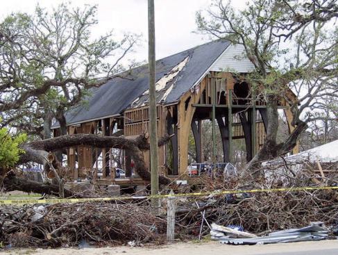
Trinity Episcopal Church used to sit on short concrete piers, about 4 feet above grade and 14 feet above sea level in Pass Christian, Miss. But when Hurricane Katrina devastated the Gulf Coast in August 2005, the 26-foot-deep storm surge left Trinity under more than 12 feet of water — enough to wash away the walls and another two buildings on church grounds, and enough to destroy the middle school across the street. Somehow, the building’s floor system, laminated arch framework, and roof survived virtually intact.

After the storm, an engineer who checked out the building feared that the frame had been too badly racked to be repaired, and he recommended that the church be demolished. But members of the church’s building committee weren’t so sure and asked my company to take a closer look. It was true that all but one of the arches were out of plumb, but my laser measurements showed they were off by different distances — from 1/2 inch to 1-1/4 inches in 16 feet — and in different directions. After inspecting the timbers and the connections, we concluded that the frame had already been out of plumb after being rebuilt following Hurricane Camille in 1969, but that it was still structurally sound.

The congregation wanted to salvage as much of the church as possible, and the decision was made to rebuild again around the existing arch frame. To make the church more hurricane-resistant and to qualify for LEED certification, project architect Leah McBride specified SIPs for the walls and roof. And to meet local codes and FEMA’s new base-flood elevation (BFE) recommendations — and thereby qualify for significantly lower insurance rates — we would raise the church another 10 feet above its former elevation, to 14 feet above ground level. That would put the finish floor of the new church about a foot above the area’s new 23-foot BFE. My company was hired to be the general contractor for the project.

Lifting the Building

Before lifting the building, we used plywood gussets to repair a number of floor joists; they had cracked lengthwise where they’d been improperly notched to fit the steel brackets tying the floor system to the original foundation. We also replaced some termite-damaged lumber, then resheathed the entire floor with 3/4-inch Edge Gold T&G panels (888/453-8358, ilevel.com).

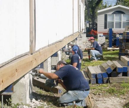
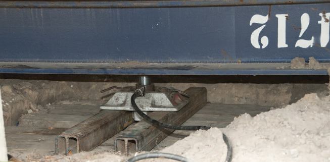
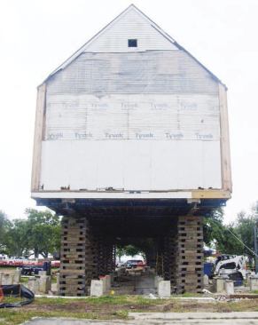
Raising a 3,000-square-foot, 66-ton building more than 10 feet was a terrifying prospect, but I was reassured when I learned that the lifting contractor — Davie Shoring of New Orleans — had 150 other buildings in the air at the same time. It took the shoring crew only a couple of days to place the two 100-foot-long main steel I-beams and ten 30-foot-long cross beams, install cribbing for the hydraulic jacks, and break the building loose from the old foundation (see slideshow).

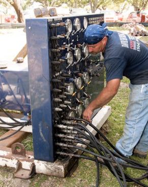
The actual lift took about 11 hours, spread out over the course of two days in May 2009. The 10 jacks were connected to a diesel-powered hydraulic pump, which raised them simultaneously at a rate of 10 seconds per 6-inch lift. Then the crew would take about an hour to install more cribbing, lower the building onto the new cribbing, reposition the jacks, and repeat the process. By the time the building reached its final position, movement over its 100-foot length was less than 3/8 inch, a virtually flat lift.