Ray Petrin
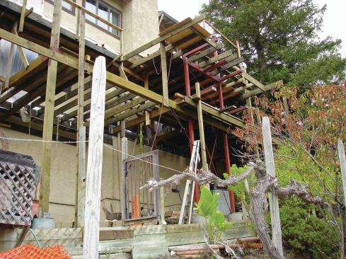
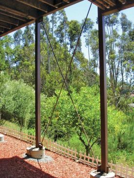
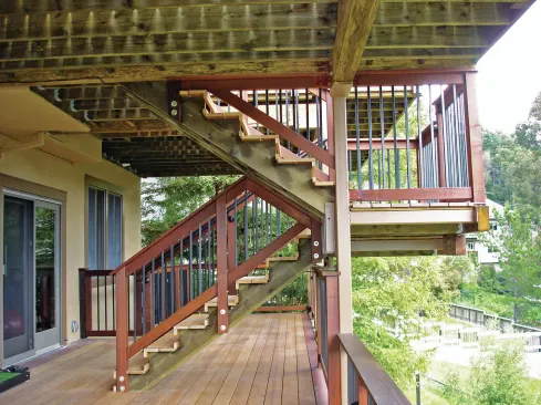
The multistory deck is anchored to the hillside by five 20-foot-…
The rolling hills of San Mateo, Calif., lie within a few miles of the San Andreas Fault. So when I was contacted to reconstruct and expand the rear decks of a hillside home there, I knew that seismic issues would be central to the project. On inspecting the existing three-story-high deck structure, I found that it was unsafe and that no part of it could be salvaged or reused. Besides having extensive dry rot and termite damage, it didn’t meet current building codes and was actually separating from the residence. It clearly would not survive a major earthquake.
Redesigning and rebuilding the multistory deck would be an ambitious undertaking. Before making a formal proposal to the clients, we needed to be sure the project would satisfy their criteria and all building codes. So we assembled a team that included an architect, a geotechnical engineer to analyze the soil the new deck piers would rest on, and a structural engineer to calculate the loads and to design the deck to meet codes, especially any relating to seismic requirements.
Foundation
The engineer’s foundation design featured five 18-inch-diameter by 20-foot-deep reinforced concrete piers. After demolishing the old structure and hauling it away, we laid out the pier locations and drilling began. Because access to the backyard was difficult, a portable rig had to be used to drill the holes for the piers, and concrete had to be delivered by a pumper truck.
Fortunately, we were able to leave the dirt spoils on site—which meant we did not need to haul as much as 9 cubic yards of soil by hand uphill to the front of the house, load it into a truck, and cart it away. Following the engineer’s instructions, we completely cleared the nearby ground of vegetation and deposited the spoils there in 4-inch to 6-inch lifts, running a vibrating plate compactor over each lift to tightly compact the area. This saved us a lot of back-breaking labor, and our clients about $3,500, not including the cost of disposal if a site could not be found to dump the dirt for free.
You never know what you’re going to find when you excavate, but in this case the drilling went well with no surprises. I’ve learned from experience to include a provision in our contracts that clearly states that extra work may be required—and charged for—if hard rock or other unanticipated conditions are encountered.
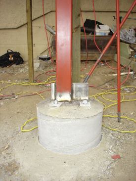
The steel cages for the concrete piers were fabricated on site using #5 rebar with #3 ties, according to the engineer’s specifications. During the pour, we embedded 1-inch-thick steel base plates—fabricated off site—in the concrete piers. Each base plate was fitted with four 24-inch-long by 1-inch-diameter J-bolts to anchor it to the pier. We used about 7 yards of concrete to complete the five piers.
Moment Frame
To resist seismic forces and control movement of the deck relative to the house, a three-story welded steel moment frame was required. The moment frame also serves as the main support system for the stair tower.
Steel moment frames consist of beams and columns joined by a combination of welding and bolting. Most modern high-rise buildings and many mid- and low-rise buildings rely on steel moment frames to resist lateral loads arising from winds and earthquakes, and they’re sometimes required for tall decks in my area. In an earthquake, lateral loads are the result of internal forces that develop as the ground—and therefore the building’s foundation—accelerates. The force, which is similar to what a passenger standing on a bus feels when it accelerates, is resisted by the bending rigidity and strength of the moment frame’s vertical and horizontal elements.
The moment frame on this project consisted of two 6-inch by 6-inch by 24-foot-tall steel columns welded to the base plates embedded in the piers. The steel columns were then connected to each other by 6-inch by 8-inch steel tubes (all 1/4-inch wall), welded into place. Two sets of 1-inch-diameter threaded-rod cross braces were added to further strengthen the frame.
I have very good steel fabricators and welders on my crew, but none are qualified to perform the AWS (American Welding Society)-certified welding required on an engineered structure like this. After we did the initial assembly of the moment frame and clamped and tack-welded the structure together, a local company that has certified welders completed the job. They worked under the supervision of special inspectors hired to oversee all the metal-working—especially the welding—on the project. Once the MIG-welding was finished, my crew cleaned and wire-brushed the welds with solvents, then brushed on a couple of coats of Rustoleum metal primer.
Hold-downs
In addition to the three-story steel moment frame, vertical and horizontal hold-downs were essential to the seismic work and had to be installed to exact specifications. In fact, a significant—and not entirely anticipated—amount of time was spent installing the many hold-downs required to connect the residence to the foundation and to the deck structure. First, though, we had to remove much of the existing stucco in order to install new treated ledgers for each deck level. These we bolted to the rim joists with 5/8-inch-diameter HDG bolts, following the structural engineer’s fastening schedule.
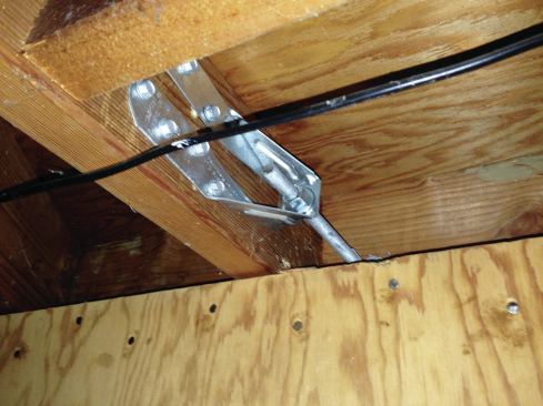
Horizontal hold-downs. Each ledger had to be connected to the house framing with Simpson Strong-Tie DTT2 tension tie hardware as well. These anchors could be attached only by removing the existing stucco—and in some cases, sheathing and interior finishes—in order to access the interior framing. Instead of specifying two tension ties per ledger (per the IRC), our engineer specified six or seven per level, in locations that corresponded to those of our vertical hold-downs.
Vertical hold-downs. We strengthened the house itself against seismic forces by retrofitting vertical hold-downs that would connect the rear walls (on all three stories of the house) to the foundation in a much stronger manner. To do this, we drilled 16-inch-deep 5/8-inch-diameter holes through the mudsill and into the existing poured concrete foundation walls. After clearing out the holes with compressed air, we glued threaded rods into them with SST two-part epoxy. Altogether, seven 1/2-inch-diameter threaded rods run all the way up the walls to DTT2s at the top plate and connect the house levels together.
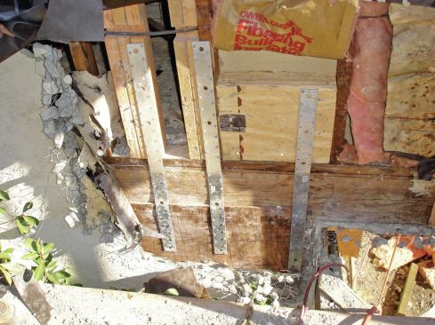
On the exterior, we installed vertical metal straps, per the engineer’s specifications, that connect the wall framing to the foundation. The straps are fastened to the foundation and nailed directly to the studs. In combination with the vertical hold-downs, the strapping helps create a continuous load path from the foundation up through the studs and all the way to the roof. For virtually all of the hold-down, strapping, and epoxy procedures, inspectors (from the county and from the engineer’s office) needed to view the completed work before the walls were closed up.
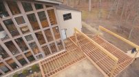
Deck Framing
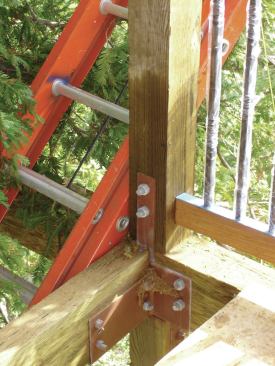
With the preliminary structural work out of the way, work could begin on the deck framing, starting with the first floor. For the most part, we framed with treated Douglas fir 6×6 posts and 4×8 girders, using standard HDG hardware whenever possible. But in addition to providing lateral strength, the steel moment frame supports much of the framing. So we also fabricated about 20 custom brackets on site from 1/4-inch and 3/16-inch steel plate and bar stock to connect the deck framing to the moment frame. These, too, had to be finish-welded by certified welders.
Finishes
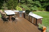
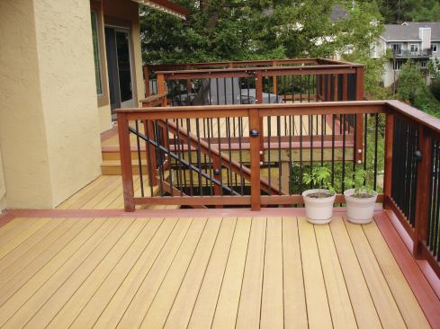
Finally, we installed the composite decking, using one color for the field and a different one for the borders to help define transitions between various areas and levels of the deck. We face-fastened the decking to the framing with GRK screws (grkfasteners.com), which have tapered heads that pull the decking down and virtually disappear, leaving a clean surface.
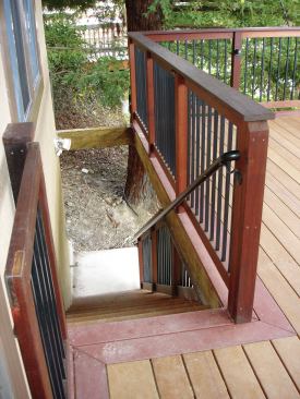
The ipe posts and rails provide not only a rich contrast to the decking but also an extremely strong railing system. We finished the guard rails with black powder-coated aluminum balusters. To meet code, the rail height had to be 42 inches, and inspectors paid particular attention to our post fastening details to make sure the rail would be strong enough. At the stairs, we also had to install graspable (between 1 1/4- and 2-inch-diameter) hand rails.
Lighting was another code consideration, since the deck would see considerable nighttime use. By code, the central tower of stairs had to be illuminated sufficiently to be used safely, so our clients worked with the architect to come up with a plan where the fixtures wouldn’t be too visible. Lighting was also required at each landing and at the entry into the house.
Cost
It took our team several months just to produce the drawings, calculations, soils reports, and supporting documents for this project. Prior to submitting them to the San Mateo County building department for approval, my clients asked for a ballpark estimate, excluding costs for permit fees or fees for the inspections that would be required by both the county and the project engineers. I calculated that the project would cost about $375,000, which would include installation of new windows and sliding doors leading out onto each level of the deck. From start to finish, my crew spent a total of eight months on site building the deck, which had a final price tag of about $386,000.
Ray Petrin owns Hy-Tech Construction in Belmont, Calif. He was assisted in writing this article by Carly Bertolozzi.