Deck Foundations
Most decks can be supported by wood posts resting on concrete footings, piers, or a combination of the two.
Size. Assuming a minimum soil bearing capacity of 1,500 psf, 8-inch-diameter concrete piers bearing on square footings measuring 2 feet on a side and 9 to 11 inches thick are adequate for most single-story decks where beams are spaced 14 feet apart or less and joist spans are 14 feet or less (see Footing Size table below).
| Beam Span |
Joist Span |
Round (diameter) |
Square | Footing Thickness |
|---|---|---|---|---|
| 8′ | <10′ | 20" | 18"x18" | 8" |
| <14′ | 24" | 21"x21" | 10" | |
| <18′ | 27" | 24"x24" | 11" | |
| 10′ | <10′ | 23" | 20"x20" | 9" |
| <14′ | 27" | 24"x24" | 11" | |
| <18′ | 31" | 27"x27" | 13" | |
| 12′ | <10′ | 25" | 22"x22" | 10" |
| <14′ | 30" | 26"x26" | 13" | |
| <18′ | 34" | 30"x30" | 15" | |
| 14′ | <10′ | 27" | 24"x24" | 11" |
| <14′ | 32" | 29"x29" | 14" | |
| <18′ | 37" | 33"x33" | 16" | |
| 16" | <10′ | 29" | 26"x26" | 12" |
| <14′ | 35" | 31"x31" | 15" | |
| <18′ | 40" | 35"x35" | 18" |
Depth. Keep deck footings at least 5 feet from a house foundation. Deck footings closer than 5 feet should be set at the same depth as the house footing. Otherwise, place footings below the frostline or at least 12 inches below grade.
Reinforcement. To prevent cracking of the footing due to point-load forces, add steel reinforcing. Make sure an unreinforced footing is not too wide. It should extend at least 2 inches beyond the pier but no more than the thickness of the footing. In all cases, center piers or posts on footings.
Engineered alternatives. For problem soils, steep slopes, or sites with difficult access, or where environmental or other conditions preclude excavation, several engineered alternatives to conventional concrete footings and piers are available:
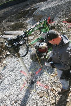
Hydraulically driven helical piles (photo above) are typically installed by subcontractors who use torque readings to achieve the required bearing capacity in a variety of soils. (For more information, see Working with Helical Piles)

Precast pin footings (photo, above) bear on steel pipes driven using a hammer drill through sleeves in the piers to a depth determined by the frostline. (For more information on pin footings, see Slideshow: On Site with Diamond Pier)
Call 811 before you dig. Whether you plan to dig holes for footings or use an engineered pier system, take the precaution of calling ahead to determine the existence and location of any underground services in the project area. In most of the U.S., simply call 811 at least three days before digging (in Canada, each province has a separate phone number for information).
For more on Deck Foundations, see Better Deck Piers.
Foundation Post Connections
While some deck failures are caused by rotted or split wood components, most are due to inadequate or deteriorated fasteners and post, beam, and joist connections. These failures can largely be avoided by selecting from a wide assortment of metal structural connectors and fasteners that are available for virtually every purpose in joining deck frame members. In most cases, structural connectors provide stronger, longer-lasting joints than nails, screws, or bolts alone.
Post-to-Pier Connections
An assortment of adjustable and stationary steel connectors are available to anchor posts to concrete piers. Some are designed to be set in wet concrete, but most can be fastened with anchors or epoxy-set in cured concrete.
Technically, pressure-treated wood posts rated for ground contact can be encased in concrete or earth, but this is not recommended. Metal post connectors are stronger and will last longer. The connectors provide resistance to uplift and are designed to allow drainage that will keep moisture away from the wood.
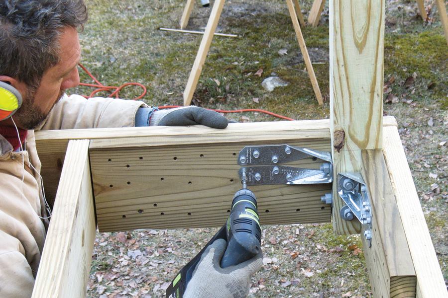
Post-to-Beam Connections
Horizontal deck beams should rest directly on top of posts. Avoid hanging beams from the sides of posts; over time, deck loads can overstress the bolts or lags.
Many types of metal brackets and connectors are available to reinforce beam-to-post connections against lateral and uplift forces. However, many builders prefer to notch post tops to let-in beams, then fasten them to the posts with structural screws or bolts. This method not only reinforces post-beam connections against lateral and uplift forces but also may be more visually appealing.
Corrosion Resistance of Deck Connectors
Because most deck frames are constructed with copper-infused pressure-treated lumber and most structural hardware is made from galvanized steel, some degree of galvanic corrosion is inevitable.
Stainless-steel hardware offers the highest level of corrosion resistance. Types 304, 305, and 316 all comply with IRC standards; Type 410 is not as corrosion resistant and is not recommended for salt air or harsh chemical environments.
When stainless steel is too costly, galvanized hardware generally offers the next-best level of corrosion resistance. But not all galvanizing processes are equally effective. Mechanically galvanized Class 55, hot-dipped galvanized (ASTM A-153), and various “double-barrier” coatings for hardware and fasteners, generally meet the applicable code for corrosion resistance. Make sure that the steel connectors and all fasteners are made from the same or compatible metal and have similar rust-preventative coatings.
As precaution with galvanized connectors, peel-and-stick flashing can be used to prevent contact between the steel and treated-wood surfaces. While this is effective in slowing corrosion, the added material and labor for this time-consuming step be as expensive as using stainless steel hardware and fasteners. However, it may be expedient when stainless-steel hardware is difficult to find.
Deck Ledgers
When decks are connected to the building, as they typically are, improper sizing, fastening and bracing of a ledger board is the single biggest cause of deck failures. The connection must support the vertical load (see Fastening Ledgers below) and well as the lateral load (see Bracing Ledgers below).
Ledger material. Solid-sawn two-by, preservative-treated southern pine or hem-fir is typical for ledger boards. The ledger should be minimum 2×8 PT #2 grade lumber or other approved material, and at least the same thickness as the deck joists.
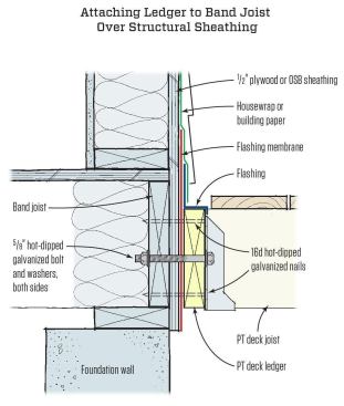
Fastening ledgers. Typically a ledger is fastened to the band joist directly or through sheathing, with either lag screws or bolts.
Conventional connectors include minimum ½-inch lag screws (with washers) or through-bolts (washers on both sides of the connection). In addition, structural fasteners are available that meet or exceed the shear design values of 1/2-inch lags or bolts. These typically come either coated or in stainless steel, require no pre-drilling, and can be driven with an impact driver or a 1/2-inch drill at low speed. Manufacturers provide size and spacing charts that will meet code, depending on the materials used and the maximum joist span of the deck.
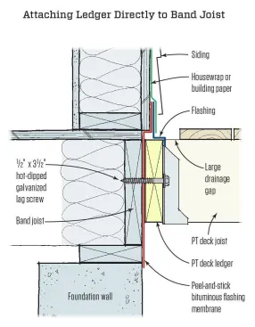
When fastening the ledger directly to the band joist, the tip of the lag screw should fully extend through the inside face of the band joist. Flash the ledger to prevent water from contacting the band joist. Stagger lags and bolts.
Instead of lag screws, through-bolts can be used when fastening the ledger directly to the rim joist as well.
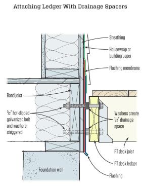
To promote drainage and reduce the risk of rot to the building and deck structure, washers can be used to create a drainage space. A thicker 5/8-inch, hot-dipped galvanized or stainless steel bolt is need because of the extra length. The maximum gap between the face of the ledger and the face of the wall sheathing is 1/2 inch.
The flashings shown in each of the section drawings above are critical to protect the structural members and fasteners from moisture. For more detail see Flashing Deck Ledgers.
Bracing Ledgers. The details for fastening the ledger described above are designed to support the vertical loads – the weight of the deck and occupants on the deck bearing down on the ledger connection. In addition, the connection must also resist lateral loads to prevent the deck from pulling away from the building.
The 2012 IRC recommends using hold-down tension hardware in at least two locations to tie deck joists to floor joists of the primary structure. The illustrations below show suggested methods for bracing ledgers when the deck joists run either parallel to or perpendicular to solid-sawn or wood I-joist floor framing.
However, though-bolted hold-down hardware is not the only way to meet the requirements of the IRC. A variety of engineered and non-engineered lateral bracing solutions are also allowed. For more on alternative connections, see Lateral Bracing Alternatives.
Ledger Support. The ledger does not necessarily have to connect to the building’s frame. One alternative is to build a freestanding deck (below). For more on this option, see Building a Freestanding Deck.
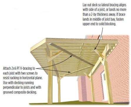
Bracing Details: 2×6 V-bracing under the deck joists stiffens the deck in the horizontal plane.
The deck can also be supported with posts and supported with connections to the building’s foundation, as shown below.
Sizing Deck Posts, Beams, and Joists
Here are some rules of thumb for sizing framing members for simple deck designs. To size framing for complex designs, or decks with long spans or multiple stories, consult your building department or an engineer.
Sizing structural posts. Most decks that are 8 feet or less above grade with beam spans of 10 feet or less can be built safely with 4×4 posts, but the American Wood Council (AWC) recommends using 6×6 posts in all cases for decks up to 12 feet off the ground. The primary reason is that a 6×6 is better able to resist bowing than a smaller dimensional post.
The material and size for structural posts for decks taller than 12 feet, or that support multistory decks, should be determined by a professional engineer. Posts taller than 12 feet may also require lateral bracing to resist bowing.
Beam and joist sizes and spans. The Prescriptive Residential Wood Deck Construction Guide (PDF), also known as DCA-6 published by the American Forest & Paper Association, offers useful span tables for the wood species typically used for deck beams and joists.
Guidance on DCA-6. For information on structural sizing of deck members and connections for decks in high-wind and flood zones, see Safe and Durable Coastal Decks.
Guardrail Posts
Deck guardrails offer builders a great chance to set a distinctive style and show off their ingenuity and craftsmanship. But plain or fancy, a deck guardrail must meet minimum requirements for strength and safety.
The key to building strong deck railings is to fasten railing posts in a way that resists the lever force exerted at the post base when someone leans against the top rail. How this is done depends on where a post will be attached to the deck frame, but here are key best practice guidelines:
- Space guardrail posts no further than 6 feet apart.
- Don’t notch wood posts around joists or beams. Use at least two 1/2-inch bolts (preferred) or lag screws to fasten the base of wood posts to the face of the joist.
- Use metal, deck-post tension ties and wood 2x blocking to counteract forces at post bottoms. See details below.
For more on building safe deck guardrails, see Code-Compliant Guardrails.
Decks Stairs
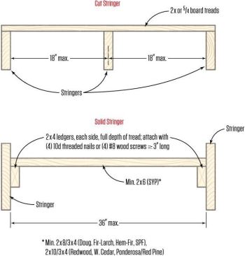
By code in most jurisdictions, a deck stairway must be at least 36 inches wide. This is also the maximum width of a stair built with closed stringers.
Regardless of the width, the stringer span is limited (see illustration below).
Note also that new design values for visually graded southern pine have changed as of June 1, 2013 (see New Design Values, resulting in changes to maximum span for both cut and solid stair stringers).
Stringer attachment. Best practice is to attach the stringer with full bearing against the deck header, and use a metal connector. Note in photo below that only rim joists made with 2x12s (or bigger) provide enough attachment surface for use with metal stringer mounting brackets.
At the bottom of the stair, stringers should rest on a footing (concrete pads or piers post footing) designed to resist a 40 psf live load and a 10 psf dead load.
Tread size. The new Southern Pine design values increase the minimum size for southern pine treads in solid stringers from 2×6 to 2×8 at a maximum of 36 inches wide. The maximum width of treads supported by a cut stringer is 36 inches.
For more on building deck stairs, see Building and Installing Deck Stairs.
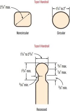
Handrails and guardrails. At a minimum, a stairway to a deck or porch with four or more risers must have a handrail on one side. Handrails must be graspable (see Handrail Grips, below) and must run continuously from the lowest to the highest riser (allowing for interruptions by posts at turns in the stair).
If the stair has a guardrail, the same rules apply to maximum spacing allowed between posts and maximum opening dimensions (see “Stair Guardrails,” below).


