If you are building a new house, one of the most important decisions is always what type of foundation to use. If you get the foundation right, you have a fighting chance of building a good house. On the other hand, with a bad foundation, no matter what you do in the build, you will have problems with the house.
Here in the South, we usually build slab-on-grade. We don’t have a frostline, so code does not require that we dig down several feet. It isn’t like the Northeast and the snowbelt states, where once you are digging below the frostline, it makes sense to dig out the entire footprint to gain usable space below grade. However, when we build on problem soils—and we have plenty—we have to use pier-and-beam foundations. In this article, I cover two examples I’ve built recently—one with concrete piers for a SIPs home on a lot with clay soils and one with steel piles for a house on the shores of Lake Austin, where the water table was only a few feet below grade.
These days, lots are scarce just about everywhere, and builders in all regions find themselves building on land they might not have even considered 20 years ago. The two foundations I describe in this article were both built near Austin, Texas, but they are foundation types that could work in any region, provided you are working with a geotechnical engineer to evaluate the specific local site conditions.
Clay Soils
Texas is full of building sites with high clay content, so we often work closely with a geotechnical engineer at the start of a project. On our recent SIPs house, we had only a foot or two of good top soil; underneath that, the engineer’s soil test showed a high clay content in the soil, extending all the way down to bedrock at about 20 feet.
The problem with clay is that it expands dramatically when it gets wet and then shrinks back just as far when it dries out. If we were to build a typical slab-on-grade foundation on clay, the house would experience a lot of uneven movement. It would pitch around, in slow motion, like a boat on rough water. This, of course, could cause windows and doors to stick, and stucco, siding, and drywall to crack.
But it can get much worse than that. Many clays are highly attractive to water, and when they expand, they do so with considerable force—enough to crack concrete footings and foundations.
Of all the soil types, clay (as well as sandy clay, silty clay, and clayey silt—all soils that vary in the amount of clay content) has the lowest bearing capacity (only around 1,500 psf, compared with rocky and gravely soils, which have a bearing capacity around 3,000 psf, or bedrock, at 12,000 psf). Clay is just not the stuff you want to build on. Therefore, the only real option for our SIPs house was to sink piers all the way through it, to support the house on bedrock. In effect, we were building something like a beach house up on stilts; though the clay was there, we were not depending on it in any way to support the house.
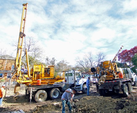
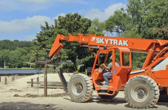
To place the piers, we worked with a drilling company to bore through the clay.
Concrete Piers
To place the piers, we worked with a drilling company to bore through the clay. I have built homes with piers drilled up to about 40 feet deep. Often, the drilling rig will bore not only through the clay but also into the bedrock—up to about 4 feet—to securely anchor each pier to the rock.
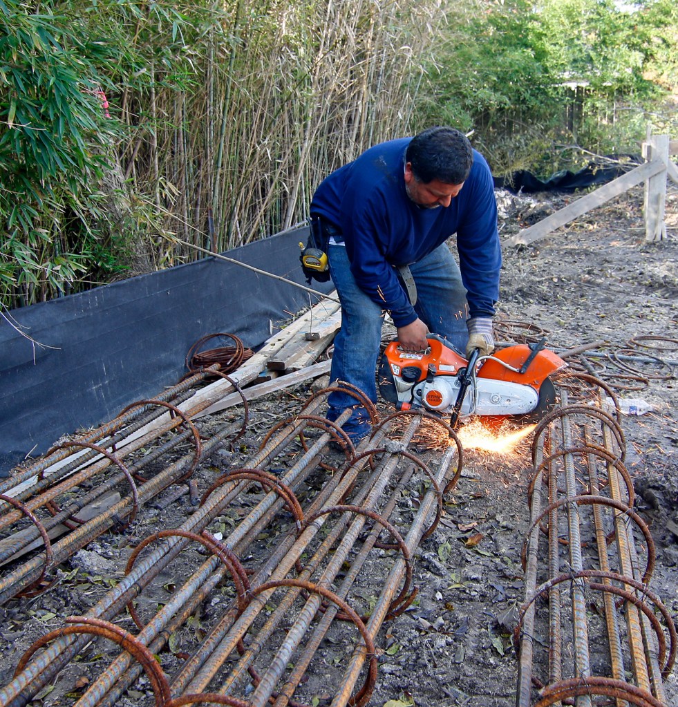
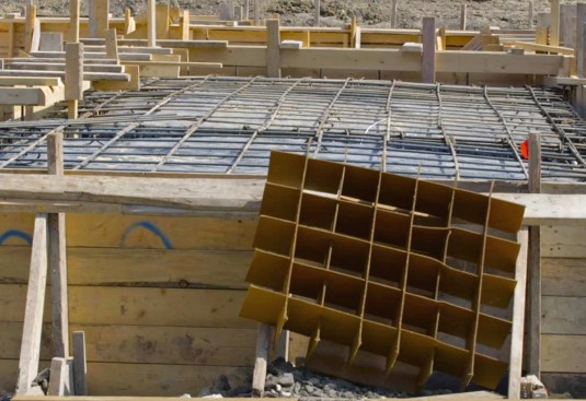
Rebar cages. The foundation crew wired up long rebar cages that extended the entire length of the boring (see photo, page 41). Once a few holes were drilled, the crew lifted the cages with the drilling rig to lower them into the holes. The holes provided the form for the concrete, and we didn’t want them filling up with dirt, so the foundation crew installed the cages and poured all the holes they could drill in a day.
The holes provided the form for the concrete, and we didn’t want them filling up with dirt, so the foundation crew installed the cages and poured all the holes they could drill in a day.
When pouring the concrete here, we needed a fairly loose mix so it would pour easily through the rebar cages without creating voids. We did not want to just water down the mix, though, but instead used a rich mix, carefully controlling the slump. The engineer was kept busy throughout the process, periodically evaluating each truckload of concrete.
The engineer was kept busy throughout the process, periodically evaluating each truckload of concrete.
Carton Forms
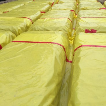
Even though the piers extended from the slab to bedrock, the clay soil could still expand upwards and crack the slab. So on this house, we isolated the slab from the soil using carton forms. In effect, these created a sub-slab cardboard box that provided enough strength to support the slab and the grade beams during the pour. The carton forms were covered with a durable, 15-mil poly, and the rebar was wired tightly, with plenty of stand-offs to keep the reinforcing in the midsection of slab. Once 4-inch mesh was laid on top of this, the concrete crew was able to work off the reinforcing layer during the pour without falling through the carton forms.
We isolated the slab from the soil using carton forms.
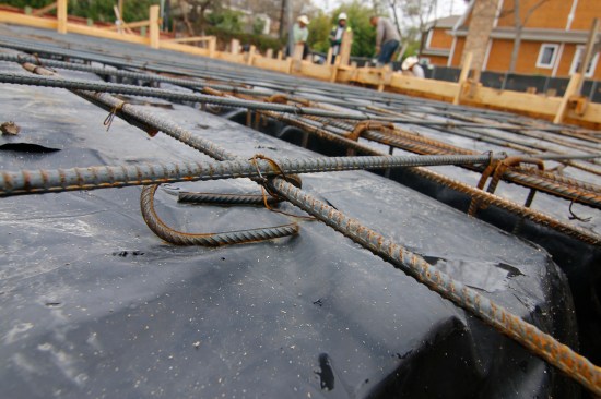
The carton forms were covered with a durable, 15-mil poly, and the rebar was wired tightly, with plenty of stand-offs to keep the reinforcing in the midsection of slab.
The rebar running through the beams interlocked with the slab reinforcing and with the pier reinforcing.
Once the concrete cured, the rebar in the slab and in the grade-beams created a self-supporting structure. The forms may crush over time, but the soil pressure will not be able to exert any significant force against the concrete.
Grade beams. The grade beams were poured at the same time as the slab, so all the concrete and reinforcing was integral. The rebar running through the beams interlocked with the slab reinforcing and with the pier reinforcing.
Perimeter beams. Around the outside of the foundation, we formed a perimeter beam that both supported the slab edges and acted as a stem wall, rising above the slab floor to create a crawlspace. (We will insulate and condition the crawlspace to be inside the building’s thermal envelope.) This gave us access to all the utilities under the house, by sleeving through the perimeter beam.
We formed a perimeter beam that both supported the slab edges and acted as a stem wall, rising above the slab floor to create a crawlspace.
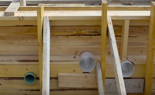
This gave us access to all the utilities under the house, by sleeving through the perimeter beam.
Termite control. Termites are a given with every foundation we build. In this region, they are often dealt with by pouring chemicals around the foundation, but chemicals inevitably leach away and become ineffective. They also create a health hazard in local waterways, so I prefer Termimesh—a tight-woven stainless steel mesh.
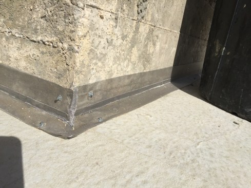
The posts were needed structurally to support the floor girder, but it created a cold joint in the concrete that needed to be protected with Termimesh.
On this build, we had a couple of concrete posts on footings that we formed up and poured before the slab. The posts were needed structurally to support the floor girder, but it created a cold joint in the concrete that needed to be protected with Termimesh. While Termimesh does a great job of sealing the smallest gaps where termites would otherwise squeeze through, remember that Termimesh is not a substitute for yearly inspections. An inspector still needs to come around each year to inspect the inside and outside of the crawlspace.
Steel Piles
The house on Lake Austin sits on a flat lot, right by the water. Lake Austin is a man-made, constant-level lake, so we didn’t have to worry about a rising and falling water level, but the downside of this property was that the water table was only a few feet below grade.
The geotechnical engineer took a core sample all the way down to bedrock, which was just a bit over 50 feet deep. He found good soil for the first couple of feet and then soupy soil all the way down to bedrock. For this condition, a structural engineer recommended steel piles, and he designed the piles to lay out in a very specific grid pattern to support grade beams, so the house, in effect, would float above the soupy mess below.
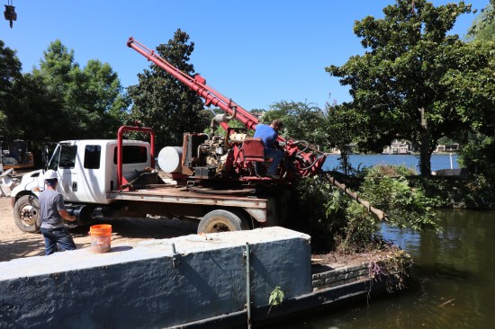
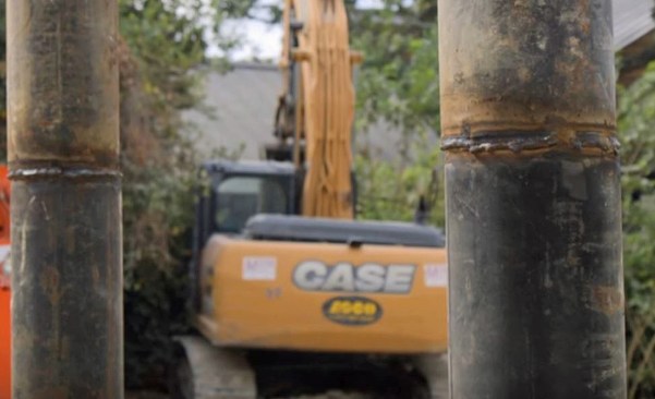
The first step to installing the steel piles was to drill holes about 10 feet deep, using a rig with a much smaller diameter bore than we needed for the pier holes on the SIPs house.
Sinking piles. The first step to installing the steel piles was to drill holes about 10 feet deep, using a rig with a much smaller diameter bore than we needed for the pier holes on the SIPs house. This provided the holes for driving each pile.
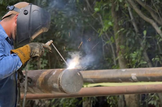
Before we drove them, we welded a steel cap on the bottom end so they would not fill up with water or mud.
The steel piles, which are made of 3/8-inch steel, 8 inches in diameter, come in 30 foot lengths. Before we drove them, we welded a steel cap on the bottom end so they would not fill up with water or mud. We wanted to keep that column free, so we could fill it later with both rebar and concrete.
All we had to do was press with the forklift.
We dropped the pile into our drilled hole with the forklift, and it was able to push the pile down the first 35 feet or so. The soupy soil offered very little resistance to pressure from the hydraulic lift. All we had to do was press with the forklift.
With bedrock over 50 feet down, we needed to combine pile sections. Once that first length was just a few feet out of the ground, we brought over a new section with the forklift and welded it on before we continued. Once we reached that last 5 feet or so, the forklift was no longer effective, and we needed a pile driver. We used a crane-supported pile driver, driving that final distance until the pile came to “refusal.”
Once that first length was just a few feet out of the ground, we brought over a new section with the forklift and welded it on.
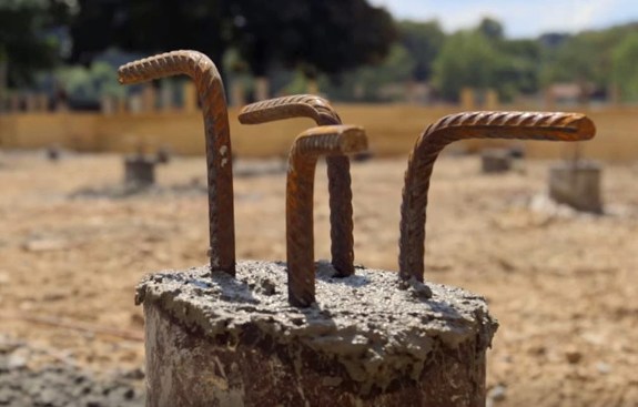
We did install rebar hooks at the top however, so we could tie each pile into the grade beams.
The steel of the pile was structural and did not require reinforcing steel for the entire length. We did install rebar hooks at the top, however, so we could tie each pile into the grade beams.
Forming the Slab
After the pile was in place to support both the house and the hardscaping, we brought in a concrete crew to form up the slab. They placed and compacted a gravel mix and formed trenches in this sub-slab surface to define the network of grade beams that would support the house.
On this project, we used 15-mil Stego Wrap, which has become my go-to vapor retarder for below-grade work.
Stego provides a super-durable seam tape …
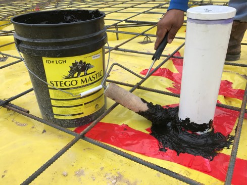
… as well as a compatible mastic, which we used in addition to the tape to seal all the slab penetrations.
On this project, we used 15-mil Stego Wrap, which has become my go-to vapor retarder for below-grade work. Because many of my projects have wood floors and other interior woodwork, I am always extremely careful to limit the amount of moisture that can wick up through a porous concrete slab. Stego provides a super-durable seam tape, as well as a compatible mastic, which we used in addition to the tape to seal all the slab penetrations.
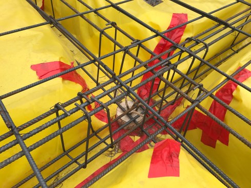
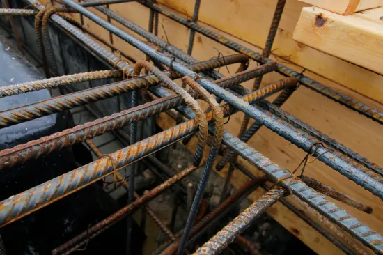
Reinforcing for the grade beams was put in first, formed in sleeves and interlaced with the piles.
Reinforcing. The rebar was a big part of the job, as it was critical to the strength of the entire foundation. Reinforcing for the grade beams was put in first, formed in sleeves and interlaced with the piles (18). Over the grade-beam steel, we laid out a precise gridwork, following the structural engineer’s design. This gridwork needed to be well supported on chairs so it would end up in the midsection of the 5-inch slab, and it needed to be tightly wired so it would stay in place during the pour. Added reinforcing was required where column bases were integrated into the slab at specific beam intersections.
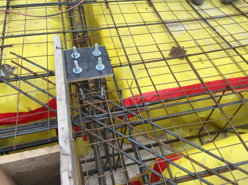
Added reinforcing was required where column bases were integrated into the slab at specific beam intersections.
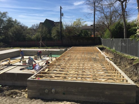
The drone shot shows the extent of the foundation for the house and the hardscaping.
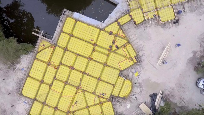
The drone shot shows the extent of the foundation for the house and the hardscaping.
Pouring the Foundation
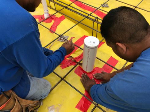
Just before starting the pour, we installed Termimesh with stainless-steel pipe clamps around all of the penetrations through the slab. The mesh was held 2 to 3 inches up from the sub-slab vapor retarder and was embedded in the concrete to create a physical barrier when the concrete dried and shrank back slightly from the pipes and sleeves (termites can squeeze through a gap as small as 1/32 inch). With the house being so close to the lake, Termimesh was the only solution possible for discouraging termites, as any chemicals were strictly prohibited.
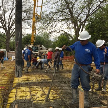
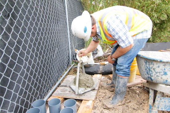
It’s critical for an engineer to be on site to evaluate the mix and for the foundation crew to vibrate the concrete.
When you’re pouring a foundation with this much reinforcing steel, it’s critical for an engineer to be on site to evaluate the mix and for the foundation crew to vibrate the concrete—particularly in the grade beams —to ensure that it is well consolidated, without voids.
On this site, so near to the lake, it was also especially important that the concrete drivers follow strict protocol, using wash-out basins when it came time to clean out the trucks.


