Cape May County on the coast of New Jersey is a low place. Its highest point, in fact, may be the local landfill. Geologically, it was about as far south as the glaciers traveled in the last ice age. We don’t have rock and clay, like they have in Pennsylvania to our north and west, and we don’t have the stony glacial till that’s found in New England. But we do have very nice beach sand and lots of it. This sand makes a pretty good base to build on—until it gets washed out.
Helical vs. Wooden Pilings
With these soil conditions, we support most of our buildings with pilings. Usually, a test piling is driven and an engineer determines how deep it needs to go to achieve the required bearing capacity. The object is to drive the piling through the questionable soil until it hits soil that offers more substantial support. For most of our projects, we aim for a bearing capacity of 10 to 12 tons.
New-construction pilings are usually made of pressure-treated wood. They’re augured into the ground to a certain point and then driven down the rest of the way with a pile-driving hammer hung from a crane. Installing wood pilings can be done pretty quickly and easily when they’re put in before a structure is built.
But wood pilings can be problematic with renovation work. To begin with, they’re long—the shortest are 12 footers, and some are as long as 30 feet. Their installation requires large equipment with plenty of overhead clearance, and the process is so noisy and jarring that some municipalities ban pile driving in the tourist season.
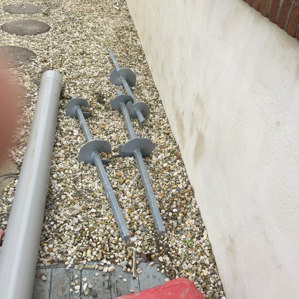
When pilings are required for a renovation in our area—or in any area that has soil with questionable bearing capacity—helical pilings can be a better option. Helical pilings are twisted, or “screwed,” into the earth with hydraulic equipment. The “threads” of the pilings are spiral-shaped plates, called “helices,” that are welded to a steel shaft. The diameter of the plates used varies according to the bearing capacity that is needed, and as with wood pilings, the total length and width of the helical pile varies depending on soil conditions and desired bearing capacity of the pilings. But unlike wooden pilings, helical piles can be installed in more confined spaces. They come in shorter sections, and once the initial section with the helices is driven, additional lengths of shaft are simply bolted on and driven in one at a time.
The Project for Helicals
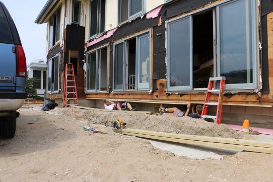
This past summer, I was hired to rebuild a porch on a house that had been built in the early 1960s. The framing of the first-floor deck cantilevered past the foundation a couple of feet on the front and rear of the home, and in a 1980s renovation, a two-story porch was rebuilt with its frame attached to the cantilevered floor. The cantilever had begun to fail—the 2×12 joists had developed a downward hook where they hung past the foundation wall.
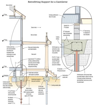
Rather than using the cantilever to support the loads of the new porch, I recommended to the owner and architect that we build a foundation wall to support the overhang from underneath. Essentially, we would be getting rid of the cantilever and creating a straight load path down the exterior wall. The most practical way to support this wall would be to build a block wall on top of a reinforced-concrete grade beam. And the most practical way to support the grade beam would be with a series of helical piles (see Retrofitting Support for a Cantilever, below).
Tim Healey
Screwing in the Piles
The first step was removing the original deck that had been added to the house. It turned out that the deck framing had been notched into treated-wood piles that were still in good shape. We decided we could use them to support the outer edge of the two-story porch.
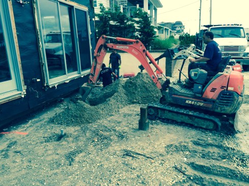
To make room for driving the pier sections under the overhanging wall, a bucket excavates a hole at each pier position. Around 4 feet of vertical clearance is needed to drive the piles.
Per the engineer’s recommendations, I laid out the eight locations for the pilings along the edge of the house at around 7 feet on-center. The cantilever was about 2 feet above grade, and the helical-piling sections were 4 feet long. So to deal with the tight space under the cantilever, we used a small skid-steer machine equipped with a bucket to excavate a hole at each of the pile locations. This gave us more room and let the installers start the pilings a little lower. After the excavation, crew members had more than 5 feet of clearance from the underside of the cantilever to the bottom of the hole.
A heavy-duty drill attachment on a skid steer drives the piers into the ground. When one section is driven down near the bottom of the hole, the next section is bolted on and the driving continues.
Although I was familiar with helical piles, this was the first time I’d had the chance to use them. To install the helical pilings, we hired Audubon Environmental, a local company with more than 25 years of experience with this type of operation. Its crew used a second skid steer outfitted with a rotating hydraulic head that turned the shaft of the piling and screwed it into the ground. The small-size machine worked well for driving the piles in the tight confines under the edge of the house.
For this project, each starting section of pile had an 8-inch-diameter helix near the bottom of the shaft and a 10-inch helix about 2 feet above that. Each piling was driven directly below the outer edge of the cantilevered wall in the excavated hole. As the shaft rotated, the helices pulled the piling into the soil. When just the end of the shaft was left exposed at the bottom of the hole, an additional 4-foot section was bolted to the shaft and the driving continued. This process was repeated until the bottom of the shaft reached a depth of 16 feet, the depth of the test pile.
Because the new grade beam would encapsulate the tops of the piles, it wasn’t critical to drive them to a precise depth. The installers simply measured off the underside of the house to set the depth.
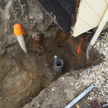
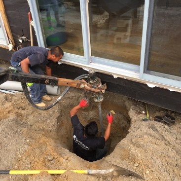
When the helical pier is close to its final depth, a PVC pipe is driven down around the shaft.
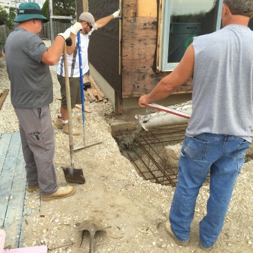
Next, they inserted a 6-inch-diameter PVC pipe as a grouting tube around the shaft of the helical pile, pushing the pipe into the soil about 18 inches past the groundwater line (about 2 feet below the bottom of the hole). The top of the pipe was cut off 4 to 6 inches below the top of the shaft. The crew cleaned out the sand from inside the pipe with a high-pressure water jet, and then they filled the pipe with cementitious grout. Once the grout had cured, they welded 8-inch-by-10-inch horizontal steel plates to the tops of each helical shaft.
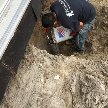
After cleaning out the PVC pipe with a high-pressure water hose, a grout mixture is poured into the pipe. A horizontal metal plate is then welded onto the top end of the shaft.
Building The Grade Beam
After all the pilings were installed, the mason, Mark McPherson, arrived to excavate a trench for the grade beam. The skid steer with the bucket made quick work of this step. The soil on the site was stiff enough to act as a form for the beam, so no additional form work was needed. And under the house, the excavation extended over to the original footing, which acted as a form for that side of the beam. The original foundation was three blocks high, but Mark opted to set the top of the grade beam at two-and-a-half blocks so that he could adjust the beam to conform to the settlement and bow of the cantilever. As a result, the grade beam encapsulated the original footing.
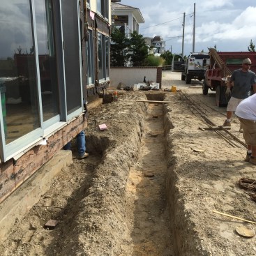
Trenches are excavated for the grade-beam footings. On the left the plates on top of the piers can be seen for the cantilever support. The trench on the right is for the footing that will support the porch. The footing will sit on top of existing PT pilings that have been cut off even with the bottom of the trench.
We also dug a trench for the grade beam that would support the new porch, and we connected the two trenches at the ends of the house. After digging the trench for the porch, we cut off the wooden piles a few inches above the bottom of the trench.
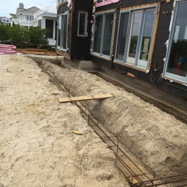
Rebar cages in both trenches are tied directly to the piles below to give the grade-beam footings their bearing strength.
Mark fashioned a continuous rebar cage that extended the full length of both beams. The cage was tack welded to the steel plates on top of the helical piles and strapped to the tops of the wood piles. The pour was straightforward with the trenches easily accessible.
Concrete goes into the trench with the dirt walls acting as forms. The existing footing forms part of the trench for the cantilever grade beam.
After the concrete cured and before Mark came back to do the block work, the crew installed new sill plates on the underside of the cantilevered joists. Mark then finished the project by laying block up to the underside of the sill plates.
Crew members attach a double sill to the underside of the cantilever. Block will be laid under the sill to support the cantilever and the new porch.
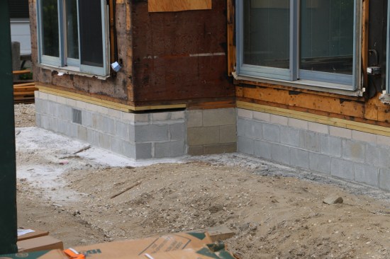
We didn’t try to fix the bow in the joists that had been in the works for more than 50 years. Instead, Mark set his block to the underside of the sill plates, which supported the cantilever and kept the bowing from getting worse. We attached the porch ledger to the original band joist, but this time the porch was solidly supported by a foundation wall and would not pull the floor joists down with it.
All photos by Nathaniel Eldon


