Where I live in the Pacific Northwest, we regularly get news reports about earthquakes and the resulting tsunami. In this seismically active region along the Cascadia Subduction Zone, which extends from northern California to British Columbia, any news of a catastrophic earthquake anywhere in the world is taken very seriously. In fact, to prepare for what many believe will be the inevitable “big one” here, some 20,000 government workers and first responders participated in the “Cascadia Rising Exercise Scenario” in June this year—a complex exercise designed to see how prepared the region is to handle a major seismic event.
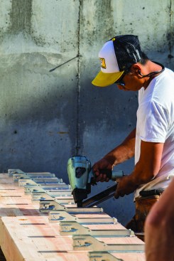
Not surprisingly, builders here have to play their part, too. Each code cycle comes with more and more requirements for keeping houses structurally safe. The majority of the seismic requirements fall on the shoulders of framers and foundation subs, whose primary role is installing a wide range of framing connectors and locating all the steel and hardware that needs to be embedded in the concrete.
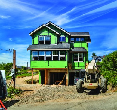
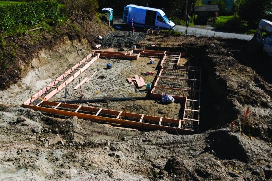
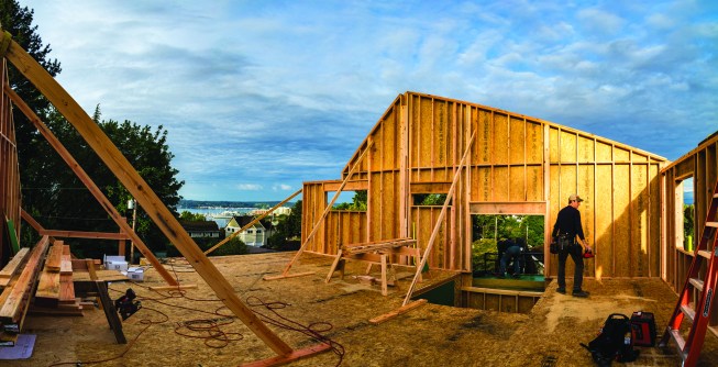
In this article, I’ll walk through my experience on a recent project we completed near Seattle—a small but surprisingly complex project that I think is representative of the type of buildings increasingly in demand in our region. Its design—a two-story house that sits over a two-car garage “basement”—provides a convenient arrangement for a hillside lot. From a seismic perspective, however, the garage on the bottom floor creates a “soft story” that is prone to collapse in an earthquake unless it is reinforced with a lot of steel—in the foundation and in the framing hardware that must be installed at every level to resist the extreme forces of seismic activity.
Taking on Foundation Work
On this project, the engineer designed the basement level to be formed full-height across the garage, meaning that the garage door headers would be poured concrete. The local building department was looking forward to seeing this constructed and required on-site inspections from the engineer of record (EOR), as well as from department officials.
Because so many details on this project had to be implemented correctly right off the bat at the footing and all through the poured-concrete basement-level walls, we elected to do all the foundation work on this house ourselves. We find that the more complicated the structural requirements in the foundation, the more cost-effective it is for us to do the forming. The job also runs more smoothly. In seismic country, there are more inspections, and doing the work ourselves makes it much easier to schedule them.
Blueprints and Engineering
A smooth-running job that comes in on budget starts with a good set of blueprints. If the plans are labeled and dimensioned clearly, then you won’t need to pay the engineer for as much time—and he is by far the highest paid worker on the project.
On this particular job, the plans were well drawn. I once had plans on which the designer didn’t dimension the walls very well—they didn’t stack directly over each other, which would have resulted in hold-downs that stubbed up in the middle of a hallway. I don’t recall the exact fix, but the memory of how irritated everyone became with this misdrawn detail sticks in my mind, enough so that comparing the different floor plans is the first thing I always do.
The RFI. Taking on the role of builder, as well as taking direct responsibility for the framing and foundation, we needed to be comfortable sending an RFI (request for information) to the engineer. In commercial work, an RFI is often a formal procedure. That’s because any changes that come back from the engineer in response to an RFI are resubmitted to the building department, and all changes supersede the plans from that point forward.
In our case, an RFI is often a fairly informal process that goes roughly as follows: When I get the plans, I pore over them, paying close attention to which walls the engineer has designated as shear walls. I also look for what kind of hold-downs are in the walls and at how the load paths are traced all the way to the footings. Essentially, I have to build the house in my head before we break ground. This is a crucial step.
If anything needs to be clarified with the engineer, I submit an RFI, requesting details and explaining why I need this information and when I need a response back. Often, the engineer either comes out to the job to answer my questions or sends me an email. Even if the changes do get submitted, the inspector doesn’t always check on the new details—as he or she might need to on a commercial project—because the town doesn’t always have time to dissect the engineering. Besides, ultimately it’s on me, not the town, to get it right.
An RFI—whether as a formal procedure that supersedes the plans or as an informal clarification of details from the engineer—is critical. When details need to be verified by an engineer, and one little detail is not discovered until you are in the field, it can get incredibly time-consuming and expensive.
Our whole process has had to change as seismic requirements have gotten more complex. In the past, we weren’t as concerned; we just framed the walls on the deck, sheathed them, and lifted them into place. Nowadays, we have to be very careful because we may not have the access we need to install all the required hardware, and we often have to stick-build walls in place to make sure we have enough room for the hardware. Our engineer constantly stresses to me the importance of making sure that anything to be embedded in concrete is located and placed precisely prior to the concrete being poured. Retrofitting a piece of foundation hardware becomes much more time-consuming and expensive.
In order to support the lower level’s full-height concrete walls (which were designed to support the two-story walls above the two-car garage), all the footings had to be considerably wider and deeper than usual.
Footings
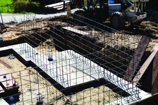
The footings on this project were much more complicated to form than those we typically see. In order to support the lower level’s full-height concrete walls, which were designed to support the two-story walls above the two-car garage, all the footings were considerably wider and deeper than usual. In fact, each run was a custom width and depth, and one area of the footings was poured as a structural slab. There was nothing regular about this job, which is why it worked out financially to form the footings in-house, rather than to sub the job out.
Each run was a custom width and depth, and one area of the footings was poured as a structural slab.
It took us about seven hours to form the footings. My process for laying out the footings was similar to that in an article I wrote a couple of years ago (“Building Stem Wall Foundations,” Feb/13). But this time I used 2×12, rather than #2 1×6 pine, to form the 12-inch-deep footings. We still staked the forms every 4 feet; even though the 2×12 doesn’t bow as easily as 1×6, we wanted to make sure the forms stayed in place during the pour. And we continued to work to the same dimensional tolerances—within 1/4 inch—for concrete work.
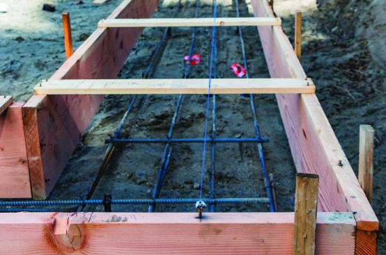
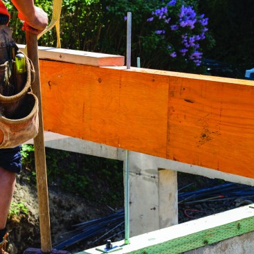
To ensure exact placement of footings, the author tacked a nail and strung a line to mark the outside of the foundation wall.
To build the footing forms, we started on a corner at the longest run. After building the corner, we marked the offset (the distance from the outside of the foundation wall to the outside of the footing) on the corner form board and tacked a 6d nail to this mark. We also marked the width of the foundation wall and labeled it. We then built the two runs out from this corner, squared those, and staked them straight.
When the opposite corner was built, we again measured for the offset and snapped a line between the marks at each corner across the top of the stretchers. This line (repeated for each run of footings) represented the outside of the foundation wall in all locations. Having this line minimized the math and need for constant measurement. Since all the runs had different offsets, we depended on having an easy visual reference. It also made it easy to know exactly where to run the vertical rebar when it came time to tie that in, before pouring the footings.
It took us the day to run all the footing forms. The next day, we finished staking the footing and then raised it to exact level all the way around using our Stabila LAR250 laser level.
Rebar
We had a lot of steel to tie in the footings; some runs had three #4, some had four #4 bar with shorter pieces perpendicular to the longer runs (the engineer called longer runs “longitudinal” and the shorter bar “transverse”). The following are a couple of rebar details in the footing that required special care:
Structural mat. We needed to tie two mats of steel in a structural footing that was 9 feet 3 inches wide by about 16 feet long. We had ordered our rebar precut so all we needed to do was assemble the mats, which we did using our Max rebar tying gun.
Of these two steel mats, the lower one had to be 3 inches off the ground. We first laid the longitudinal and transverse rebar within the lower mat, tied it together, and then supported the mat on chairs.
Next, we tied together the second mat and held it down 2 inches from the top of the form on 2x4s that we laid across the top of the form to span the width.
The string line also allowed exact positioning of the steel “verts” that were tied into the footings.
We had one hold-down bolt to locate in the structural mat. Again, having nails tacked showing the location of the stem wall made this easy. We tied in the hold-down bolt and also dug out underneath it to make sure it had proper embedment.
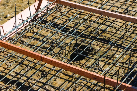
The structural mat required two grids of steel, one sitting on rebar chairs and the other hung from 2x4s laid across the forms.
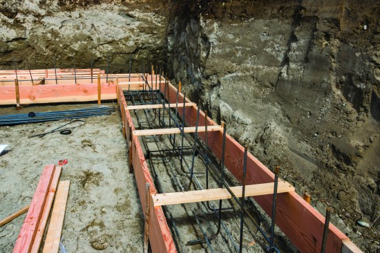
“Verts.” We needed to tie the shorter vertical steel—“stubs” or “verts”—into the footing at a specific spacing. Per the engineer’s notes, these needed to be placed with the hooks alternating direction. Since we had snapped lines across the top of the 1×4 spreaders, we knew exactly where to place our verts in the wall. We then placed a long stick of rebar on top of the cleats, tying the verts to this, as well as into the footing steel. The Max rebar gun made this easy work.
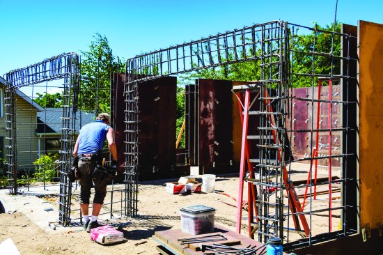
The garage openings required a steel frame formed out of rebar within the concrete walls.
To tie this into the footing, the rebar verts had to be positioned precisely.
Garage portal walls. The garage openings required a massive amount of steel to create a moment frame within the concrete. In the narrow portal walls, the vertical steel on this frame had to tie into the footing steel. I used a 2×12 cut-off to lay out the position of the steel for these verticals and drilled it out to hold the steel precisely where we needed it in the portal walls.
Foundation Walls
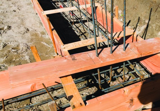
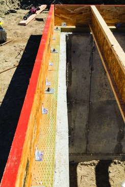
After we finished placing the footing concrete, we ran a dry line—using the same 6d nails that we’d placed in the form boards to mark out the position of our foundation walls—and set spreader cleats for the foundation wall forms. We used 1-1/2-inch x .131 Teco nails to keep the cleats in place on top of the green concrete.
After footings were poured, cleats were installed on the green concrete with “Teco” nails.
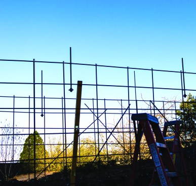
Before placing the forms, we had to tie full-height vertical steel onto the verts that were tied into the footings. We first took our precut bar and spray-painted the horizontal layout. This made it easy to get the exact spacing, and it made it easier for the engineer of record (EOR), who served as the special inspector for the town, to inspect the steel placements.
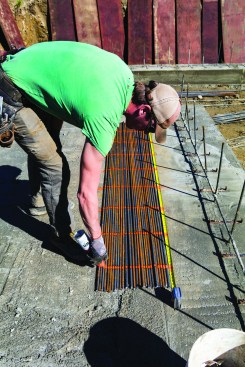
The position of the horizontal runs was spray-painted on the rebar that would be used for the verticals …
… in the rebar gridwork for the walls.
Using our rebar tying gun, we very quickly tied the vertical steel, one man scattering and holding the bar while the other man tied it off; it took only about 15 minutes to tie off the verticals for the entire foundation. After lunch, we spent a little over an hour tying the horizontals in place. We were able to speed up the process of tying in the horizontals by ordering full-height 30-inch-by-30-inch corners. This way, we didn’t need to bend them on site—which the engineer also wanted to avoid because that can cause small cracks on the rebar. It also allowed us to plumb the corners before tying two runs together and helped us keep the rebar centered within the wall section, which was also critical from an engineering standpoint.
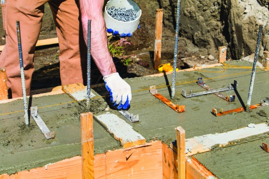
Before the formwork was erected, the crew positioned the anchor bolts.
As a last step before setting the wall forms, we tied in the hold-down bolts, using the layout defined on the plans to locate the hold-downs precisely. We installed the forms around the garage portal walls and header last, keeping them open until the engineer inspected them.
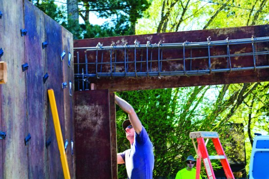
Around the portal frame, the forms were left off to allow inspection.
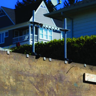
For a Simpson Strong-Wall to be installed in the front wall, a template first needed to tie into the foundation.
At the garage opening, we also had to lay out the template and tie in the large bolts for the Strong-Wall wood shear walls. These Simpson Strong-Tie panels were specced by the engineer and were needed in the wall frame above the garage door opening to provide shear resistance next to the cantilevered nook that would be framed in.
The Simpson shear walls are pretty cool. They were originally a Weyerhaeuser (I-Level) product and we used them in 2009, before Simpson acquired them. They give you more flexibility for drilling holes in them to run electrical than you would have in site-assembled shear-wall sections. They call be ordered in heights up to 141-1/4 inches and cut to length in the field.
Bracing forms. Once the formwork was erected, the last step was to brace it all off and build scaffolding for placing the concrete. I also tacked a 6d nail and strung a line for the J-bolt locations. I measured this out, too, wanting to make sure none of them landed where an I-joist would sit.
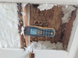
Concrete mix. The engineer specified minimum 3,000-psi concrete for the portal walls. I ordered a mix that would be 3,500 psi from the batch plant. The city where we were doing this work required that we have a special inspector on site to take samples during the pour so that the strength could be verified; the first strength test, at seven days, showed 4,200 psi.
Framing
As framers, we need to know the plans inside and out. When studying the plans for the first time, I like to start at the roof and work down and make sure I understand how everything will supported. Only then can we build from the bottom up.
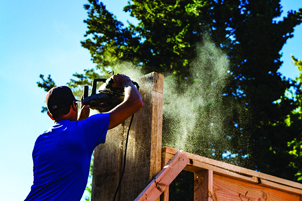
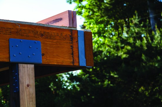
The engineer specced beams under the shear walls that had to be drilled out for hold-downs.
On this project, I had to make sure to trace the interior shear walls from the top floor all the way down. The engineer had located beams under the shear walls in the frame that were bolted down to the top of the foundation walls. We had to drill through the beams and run the threaded rod up through them either to a hold-down above or to a nut and washer. Because we went from 2×6 walls over 5 1/2-inch beams to 2×4 walls on the upper floor, I needed to make sure I kept the plane on the front wall consistent. Again, good plans helped us identify these details early on.
With the exception of the drilled beams, the floor framing on the main floor was straightforward. To simplify the foundation work, we asked the engineer if we could run the portal walls straight and eliminate the foundation jog (one that mirrored the jog in the framed wall above in the original plans). He approved that change, and we designed the front cantilever beam to hang off inverted and offset hangers. We then framed the cantilevered walls where the foundation originally had jogged, saving a lot of time.
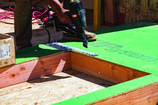
A23 corner brackets secured the mudsill to the rim joist.
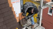
After the rim was on, we had to install A23 framing angles—the ubiquitous framing angle required in seismic country to maintain load paths every 16 inches from rim to mudsill.
Whenever possible, strapping was nailed on before the walls were lifted.
On the main level, we had some special details on the cantilevered wall. This wall was full of windows, without much sheathing, so the engineer specified a lot of strapping to tie it all together. We sheathed the walls before lifting and were able to install most of the strapping before lifting, so we didn’t need to get on ladders later.
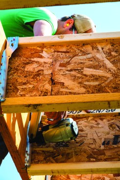
Production framing in a seismic zone is largely a thing of the past. You can’t expect to speed through the framing and then install the hardware. Instead, we typically need to install hold-downs and strapping as we are installing wall and floor sheathing. In several locations on this project, we had to leave off a panel of sheathing so the inspector could see the hold-down. We sometimes have to wait for this inspection before the next stage of framing, or we lose access to the hold-down.
Working off ladders can be very time consuming, so whenever the crew could, they attached joist hangers to the floor structure before it was lifted into place.
It is possible to be efficient, though. For example, we think ahead as much as possible, so we left room for a positive placement gun to speed up the process of installing the hardware. On the upper floors, we installed all the hangers on beams before lifting them into place, which saved time. But that’s not always possible. On the rear 2-foot cantilever, we had to install hangers to the rim joist upside down, and we had to do it after installing the rim.
Some of the hangers had to be installed in place. One example was the inverted hangers used to secure the rim on the 2-foot cantilever on the back of the house.
On the upper floor, we framed rake walls first, then the rest of our exterior walls, again adding all our strapping before lifting. With the rake walls in place, we set the ridge, then balloon-framed a two-story shear wall below part of the ridge. This balloon-framed wall locked everything together and was helpful, as we could use fewer wall braces when we framed interior walls.
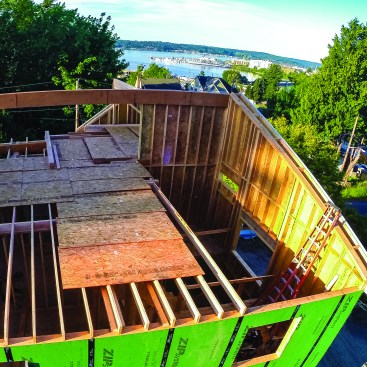
Then a two-story balloon-framed wall was installed below the ridge.
Vital Communication
Close communication with the engineer and the other trades is vital. Everyone involved must talk together to understand what’s required and to make suggestions or clear up any misunderstandings. Sometimes, what we have to build needs to be adjusted, because of plumbing fixtures or the need to get insulation into framing cavities. Those details need to be figured out ahead of time. Constant cooperation is necessary; no one trade by itself, including the engineer, will have everything figured out ahead of time. Sometimes, there is a better way to build things, and having a good relationship with your engineer will make it easier to suggest and work out an equitable solution for all.