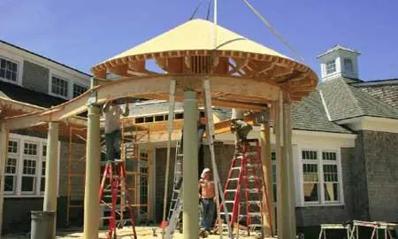
My business, Narragansett Housewrights, provides custom millwork and architectural components to builders here in southern Rhode Island. Last year, my best customer, Baud Builders, gave me the job of building a screened pavilion for a shingle-style waterfront home. The pavilion swept out in a curving wing from a corner of the building, terminating in a conical roof supported on a semicircular colonnade.
I only take on projects that I can build in the shop and deliver to the site in sections for assembly. If I had built this one according to the architect’s framing plan, it wouldn’t have been transportable. So I came up with an alternative method that I believed would also cut the build time by half. We bid the job accordingly, and after much discussion got approval from the architect and engineer to proceed.
Custom Trusses
I typically skip shop drawings and begin instead by making a simple model, in this case a section of the conical roof. This gives me a fast, simple way to view the critical components at full scale in three dimensions. Basically, I cut short pieces of each element in the structure and stick them together with hot-melt glue.
I envisioned the overall framing as four independent truss-framed modules joined together in the finished assembly: a half-cone, two sloping side modules, and a flat-topped center section. My trusses are nothing more than 2-by members connected with plywood gussets.
I designed the conical module around a series of identical triangular trusses fixed in a radial pattern around a central “hub.” The roof sections connecting the cone to the main house use a similar system of trusses arrayed along their respective framing lines.
The trusses’ tails bear on a curving architrave, a custom-made structural beam supported on six 4×6 posts concealed within hollow architectural columns. One of these columns was pre-existing and provided a point of departure for the new layout.
Moment frame. Two of the architectural columns surround steel posts, part of a welded moment frame needed to resist wind-racking and uplift. The roof modules fully encase the horizontal steel member, a W8x21 hot-dipped-galvanized I-beam.
Templated construction. To make sure that site and shop layout remained consistent with each other, I cut two identical sets of plywood templates to outline the architrave and pinpoint all the column locations. I brought the templates to the job site and laid them out on the masonry deck, then took lots of triangulated measurements off the building. I recorded these directly on the templates. Back at the shop, I used the triangulations to snap accurate layout lines on the floor so that I could position the templates exactly as they were on site. Meanwhile, one set of templates remained at the job site for locating and pouring the new column bases.
Curvy architrave. I made the architrave in three segments — the first with a 28-foot radius, the second a semicircle with an 8-foot radius, and the third a straight length of LVL. To make the curved beams, I glue-laminated 11 layers of 3/8-inch plywood underlayment bent around shop-built forms. I used Excel One, a spreadable polyurethane adhesive (800/779-3935, excelglue.com), and a boatload of bar clamps. The adhesive sets up in about five hours.
Because plywood doesn’t bend with smooth, perfect uniformity, the laminated beam had a somewhat irregular face. To compensate, I used a router on a long trammel arm to cut slightly wider, perfectly accurate top plates from 3/4-inch MDO (medium-density overlay) plywood. We centered the plates on top of the beam segments and glued and screwed them in place. Later, after on-site assembly, I gauged the Azek fascia off the plates’ edges and shimmed the inner and outer pieces in perfect parallel.
Conical framing. I began framing the semicircular conical section by building a hub, a 2-foot-diameter half-cylinder made of staves cut from an LVL beam. It’s glued together with West System epoxy (866/937-8797, westsystem.com); for added mechanical strength, I bound the staves with four perforated steel straps. The staves — which are 1 3/4 inches wide on their outer face — provide faceted surfaces for attaching the 2-by trusses.
We set the trusses on the semicircular architrave and screwed them to the hub from the back, using 4-inch Timberlok screws (800/518-3569, fastenmaster.com), one each into the top and bottom chords.
The truss tails landed at about 20 inches on-center. To create more solid backing for the curved fascia, we glued and screwed lookout blocks on 6-inch centers to a length of 1-by cedar, then nailed this assembly to the truss tails, effectively tying them together.
We then sheathed the back of the half-cone with a single layer of 3/8-inch plywood, cutting holes between the webs for access and air circulation. We added cleats on top of the plywood to catch the lower-pitched abutting roof sections. (It would have eliminated compound valleys and simplified construction if the cone and the connecting roof were the same pitch, but I lost that argument.) I left the top of the cone flat, about a foot short of the peak, to be filled in after the adjoining sections were framed and sheathed.


