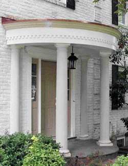
Long ago, I was asked to build a curved portico by adding a roof structure and columns to an existing semicircular front porch on my client’s Greek Revival-style home. The critical dimension for the new roof structure was the outside arc of the existing masonry porch below, which the new roof would have to match. And since the curved crown molding had to be special-ordered to size, accurate layout of the structure’s outside arc was vital for a good fit.
Working on a circular rather than a rectangular shape requires a different mode of thinking. All of our layout would need to start at the outside of the crown and work inward toward the center. So instead of a lot of complex math and “air framing,” I decided to take the same simple approach I use to build gable end walls: Lay out and cut everything on the ground.
Using a Layout Table and Trammel
To minimize confusion, we built a layout table — basically an 8-foot-by-12-foot drawing and cutting board — with three full sheets of 3/4-inch plywood fastened to 2×4 sleepers on the garage floor. Because most of our layout would originate from the center of a circle, we snapped a centerline down the middle of the layout.
Then we used scrap 3/4-inch plywood to construct a trammel arm. Fastened to the centerline with a screw acting as a pivot point, the trammel allowed us to quickly and accurately draw arcs and cut all the required curves for the project. We did our circular cutting with a router screwed to the trammel board.
Working in full scale from the architect’s plans, we drew all of the construction details on the layout table, using the 10-foot 10-inch porch diameter as the reference dimension. By working outward and adding together the trim elements, we were able to determine the exact diameter of the crown molding; working toward the inside, we were able to determine dimensions and locations of the key framing elements and the various components of the semicircular structure underneath.
The author drew the circular dimensions for the curved porch at full scale on the layout table, then laid out the framing to fit. Short 2×4 studs on 6-inch centers were screwed between the plywood plate and roof sheathing to support the curved subfascia made from two layers of 1/4-inch plywood.
Precutting the Parts
Once we were satisfied with the layout, we began using the trammel to cut out the parts, starting at the top with the roof sheathing. First we screwed three pieces of 3/4-inch CDX plywood to the layout table to give us a piece large enough to form the entire roof section. To cut around the roof’s perimeter, we set the bit of our router to cut 1/4 inch deep; a few successive passes, each one 1/4 inch deeper, got us through the plywood in about three or four swings of the tool.
Next, we cut the base of the structure, the 18-inch-wide curved plywood plate — or “subsoffit” — that would support the rafter framing and be supported by the decorative columns. The tricky part here was to back off the correct distance from the perimeter of the roof to allow for the thickness of our sheathing, trim base, and dentil blocks, as well as our crown molding. By previously drawing the location of each element on the layout table, we could see exactly where we needed to make our circular cuts.
The plate was cut out of two rippings of 3/4-inch plywood wide enough to cover the inner and outer arcs that we had drawn on the layout table. (Note: It’s easy to confuse the measurements on the trammel. If the cut is on the outside of the circle, take the measurement from the pivot to the inside of the bit; for inside cuts, measure from the pivot to the far side of the bit.) Using a radius drawn from the center of the circle, we also plotted the angle cuts for the plywood where the two sections would meet.
Once the plate sections were cut to size, we screwed them down into position on the layout table, then laid out the framing so that it would fit inside the curve of the portico. That made it easy to snap header, ledger, and rafter locations on the plywood. Now it was just a matter of measuring each piece, cutting it to length, and fitting it to form the structure; no math involved here, just simple measurements. We could even plot the column locations on the plate while working in the garage.
Assembling the Parts
After bolting a 2×8 ACQ ledger to the masonry to support the upper end of the rafters, we used temporary 2×4 posts and a few screws to support the plywood base plate. With the layout already marked on the plate and ledger and all the framing cut to length, the parts went together quickly. We joined the three roof sheathing sections together by screwing plywood scabs across the seams, then lifted and installed them in one piece.
To build the vertical structure between the bottom plate and the roof sheathing, we laid out and installed 2×4 cripples. Fastened 6 inches o.c. around both the inside and outside perimeters, these short studs support the two layers of 1/4-inch A/C plywood sheathing that we used to wrap the structure. Because we layered the plywood and staggered the seams, the curve faired out nicely, providing a smooth base for the fascia trim.
Cellular PVC Trim
With the trammel already set up to cut the plywood plate, we cut the matching base cap from 1/2-inch-thick Azek PVC material (Azek Trimboards, 877/275-2935, www.azek.com). The base cap would be attached later to the underside of the plate to create a finished soffit. Because Azek is available in 4-foot-by-8-foot (and longer) sheets, we were able to make the base cap from only two pieces of material.
PVC trim has limited compressive strength, but on this small porch the loads wouldn’t exceed 1,000 pounds per column; to minimize point-loading, we cut and fit the columns carefully and belt-sanded the tops smooth for full bearing where they would support the soffit. On a larger, heavier structure, we’d have cut the Azek to fit around the bearing points.
In addition to being durable, Azek is easy to work with, and I felt we’d be able to bend this thin 1/2-inch stock to fit the curves around the inside and outside fascia. However, wrapping the fascia with Azek proved to be a challenge in chilly weather. While PVC trim is fairly flexible, we found that Azek’s cellular structure does not react well to impacts when the temperature approaches freezing and the material is under pressure. When we flexed a piece and shot a nail into the center of the flex, the piece snapped.
So we started in the middle of the lower fascia board and worked toward the ends, screwing with stainless trim screws along the top edge where it would be covered by the overlapping fascia above. Then we carefully clamped and nailed the bottom edge as we slowly wrapped the boards around the outside radius.
After wrapping the fascia, we made and applied matching Azek dentil blocks. First, we glued the back of each block with Azek’s proprietary glue, which is similar to plumber’s PVC cement but with a lot more working time; then, to temporarily hold the blocks in place while the glue dried, we pinned them with a Senco micropinner. This tool leaves such a small hole you can’t see it, even up close.
Next, we installed two columns to support our structure, with split columns against the wall just for show. Besides having to reinforce the masonry stoop with piers below frost level and fudging the stoop’s slightly irregular shape, the only hitch we ran into here was meeting the new wind-load regulations. Since we chose to use hollow composite columns, I had to figure out a way to securely tie the roof to the masonry stoop below. So we bolted brackets to the concrete, attached aircraft cable to them, fished the cable up through each column, and bolted the cable to the rafters above after setting each column.
As we finished the interior vertical surface of the fascia, we wedged the top edge of the trim boards against the framing, slowly bent each board into position, then held it there with bar clamps instead of screws or nails. When we cut the last piece and snapped it in place, friction held everything tightly so that we didn’t need to use fasteners — which would have snapped the Azek in two at such a tight radius.
To finish off the ceiling, we used Azek beadboard, centering the middle board on the centerline and then working toward each corner. We used a cutoff (from the cap trim) as a template to scribe the cut line where each board met the inner curve, positioning the template with two measurements — the long point and short point — which we determined by measuring off the previously installed ceiling board. Since the joint along the fascia would be covered by trim, we didn’t need to finesse the scribing.
Flexible Crown Molding
Finally, we built a base for the flexible 45-degree crown molding that would finish off the top of the fascia. Made of polyester resin and available from several manufacturers, flexible crown must be special-ordered for the specific radius you plan to wrap. Because we needed enough to wrap half of a circle measuring approximately 10 feet in diameter (with a circumference of 31.4 feet), I had ordered two 12-foot-long pieces, the shortest length available (see sidebar).
Working in Circles |
|---|
|
Getting accurate measurements when doing circular work can be a little bit tricky. To calculate an order or rough-cut a piece, the key measurement is the circumference of a circle, which is easy enough to calculate (circumference = Π x diameter). When the formulas get more cumbersome, I use my Construction Master Pro calculator, which has many built-in circular functions. For example, I can determine the length of a wrapped piece (an arc length) if I know the radius of the circle and take a straight line measurement (a chord length); or I can figure it out by measuring the chord length and the rise (see illustration).
It’s also possible to physically measure small pieces of trim along a curve, though it’s difficult with a standard steel-tape measure. Instead, use either a tailor’s fabric tape or FastCap’s ProCarpenter FlatBack tape (888/443-3748,
www.fastcap.com); either will lie flat and wrap around a curved surface without distorting (see photo).
The FlatBack tape measure’s straight blade allows it to lie flat along a curved surface.
|
To provide nailing for the crown, we cut triangular chocks out of 2x4s, set them into construction adhesive, and pinned them to the bottom of the roof sheathing. Then we wrapped a full 12-foot length of crown around the middle section of the fascia so there would be two offset joints at the sides instead of one more visible joint along the center. At first we tried scarf joints to join the two shorter side sections, but we weren’t happy with the results. So we simply cut butt joints, backed the joints with small wood shims, and used Marine-Tex FlexSet (ITW Philadelphia Resins, 215/855-8450, www.marinetex.com) flexible epoxy adhesive as both an adhesive and a filler. Like Bondo, this two-part epoxy can be sanded to a fine finish, but it has a longer working time and is white when it dries, so we used it with the Azek, too.
The portico’s EPDM rubber roof was glued down over insulation board. First, though, the roofer dressed up the edge of the roof with a curved copper cap, then flashed the wall with a matching copper flashing tucked into the brickwork. The electrician installed the client’s light fixture, and later we returned to put in a new fiberglass entry door.
Our client loved the look of the porch trim so much that we ended up replacing all of the home’s exterior millwork with cellular PVC. And while I’ve recommended that 100 percent acrylic paint be applied over the new trim, it seems that they like it just the way it is.
Mike Sloggattis a remodeling contractor in Levittown, N.Y.