
Daniel Lewis
Ryan and Mike Dangelo, of M.J. Construction, in Centerville, Mas…
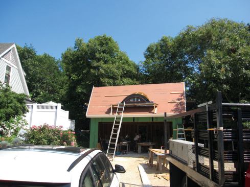
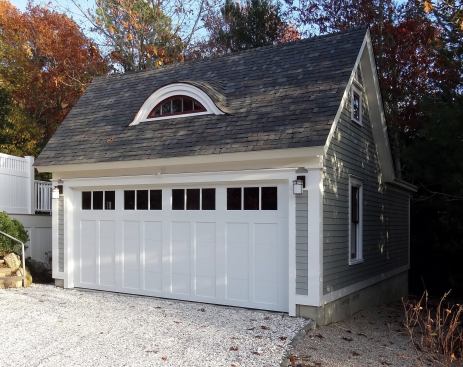
Last year, I designed and built a detached garage for a home on Cape Cod. I decided to enhance the garage roof with the graceful curve of an eyebrow dormer, a distinctive architectural element that, sadly, isn’t as common as it once was. The difficulties of building the curved and sloped details are most likely the reasons for its decline in popularity.
I started looking around in design books and online for hints on how to build eyebrow dormers and found that most approaches entailed some sort of trial-and-error process involving pencils and string and the fitting of oddly shaped pieces. Often the dormer was assembled or mocked up on the ground before being lifted into place.
I figured that there had to be a better way. The curves, slopes, and concentric layers of trim were certainly a challenge to build, but now that nearly any type of structure can be drawn on a computer, I decided to streamline the building process by designing the dormer and all of its components using my CAD (computer-aided design) program. With my plotter, I could then create full-size patterns of each component.
Ribs Vs. Rafters
As with most types of dormer, the roof construction of an eyebrow dormer is a key part of the design. In my research, I found that eyebrow dormer roofs are usually built in one of two ways: Most designs use rafters to support the roof, and some frame the roof with curved ribs that parallel the front face of the dormer.
My first inclination was to go with rafters, but after tinkering with the initial design in my CAD program, I realized that the design process would be more straightforward with curved ribs. With 24-inch-tall laminated veneer lumber (LVL) being readily available, I had material wide enough and strong enough to make the ribs, so that was my obvious choice for framing the roof.
The Design
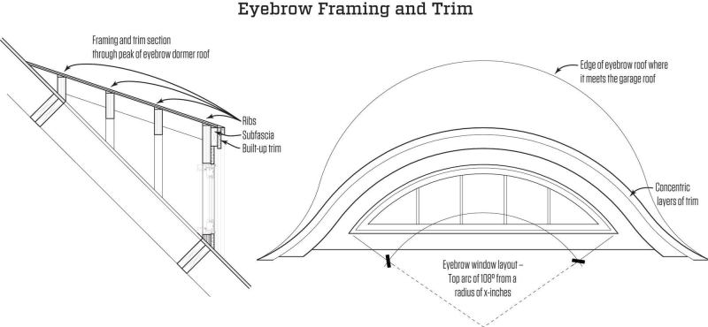
Once I’d determined the framing strategy, the next critical step was to create an appropriately scaled and visually appealing design for the dormer. In many of the images I looked at, the windows were semi-circular, but they didn’t look quite right in the eyebrow configuration. So instead of a half-round window, I opted for a window where the curve is an arc of a circle and the sill is a chord of that circle. As the initial design took shape in my CAD program, I decided on an arc that spanned 108 degrees (see Eyebrow Framing and Trim illustration, above).
I also noticed that many eyebrow dormers have a flat, one-dimensional facade, probably to make the construction easier by avoiding the need to make multiple layers of curved trim. But I wanted to give the front of the dormer some dimension and visual complexity. So as I finalized the design, I added a layered fascia to the trim around the window.
Once I had determined the exact shape and the dimensions of the window, I was able to special-order it from Andersen through my local supplier.
Lay Out the Pieces in CAD
After defining the rough opening, I completed the layout for the rest of the dormer in my CAD program. The easiest of the elements to lay out were the subfascia and the fascia trim. They each had the same outside radius as the front elevation of the dormer and I could project them directly from my design drawings. I decided to use a single piece of trim around the perimeter of the window, reducing the trim’s radius by 3 inches to accommodate the subfascia.
For the first LVL ribs, I made the radius 1/2 inch less than that of the fascias to accommodate the roof sheathing. Based on the roof pitches of the garage (12/12) and the dormer (4/12), I reduced the height of each subsequent rib, using smaller segments of the same curve for each. For even support of the dormer roof, I spaced the ribs at 10 1/2 inches on-center. The first rib (or the front face) was 27 1/4 inches high, so the second rib was 27 1/4 inches plus 3 1/2 inches (the rise of a 4/12 pitch over 10 1/2 inches) minus 10 1/2 inches (the rise of a 12/12 pitch over the same distance), which equaled a total height of 20 1/4 inches. Using this approach, I easily created the patterns for the rest of the ribs.
The sheathing for the eyebrow roof was a bit more challenging to lay out beforehand. It required projecting the lines out in steps to develop the final shape (see Projecting the Roof Sheathing Pattern, above). I started with the front elevation of the sheathing, which in this case matched the curve of the subfascia. The front edge of the sheathing (at a 4/12 pitch) was at a slight angle to the plumb face of the dormer, so to create a flat sheathing layout, I first needed to draw the face perpendicular to the dormer roof, which “shortened” it, as shown in step 1 in the illustration, above. I’d determined earlier that the front face of the dormer was 27 1/4 inches high when measured plumb, but when measured perpendicular to the 4/12 slope, the distance from the top of the face to the plane of the garage roof was only 25 7/8 inches. This meant that the outline had to be multiplied by 0.949 (25.875 ÷ 27.25) to find the perpendicular configuration.
In AutoCAD I created a block from the shape and typed in 0.949 as the vertical multiplier. I divided the perpendicular curve into 6-inch segments (step 2) and projected lines up to the non-shortened (plumb) front elevation (step 3). From there I projected the lines over to a side elevation of the dormer (step 4). At this point the lines continued parallel to the pitch of the dormer roof, with each line terminating at the pitch of the garage roof (step 5). From there, the lines extended perpendicular to the dormer roof to a flattened view of the dormer roof from above (step 6). In this view I then extended a second set of lines at 6-inch intervals perpendicular to the front edge of the dormer (step 7). In the resulting grid, I simply connected points where the two sets of lines intersected to plot the curved outline of the sheathing that could be used as a cutting pattern.
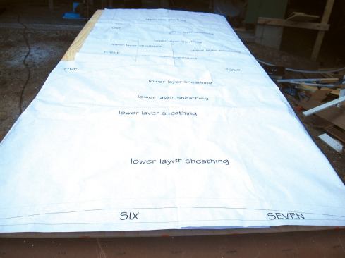
With the computer doing the heavy lifting, the process was less complicated than it sounds. Because the sheathing was to be made out of two layers of 1/4-inch plywood, the upper layer needed to be slightly larger than the lower. I made separate patterns for the two layers, but there was probably no need to be that fussy. With the patterns drawn on the CAD program, I simply placed them over the outline of 4×8 sheets of plywood. To overlap the seams of the sheathing, I drew the bottom layer to span the curved top of the roof, while the upper layer was split at the top. I included extra material along the front edge of the sheathing for a margin of error, which was trimmed back once the pieces were fit.
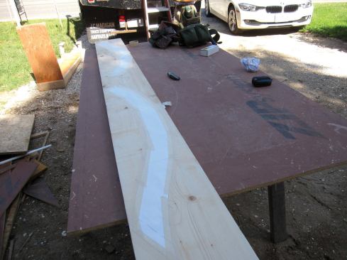
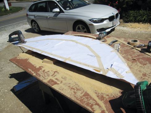
After everything was drawn, I scaled and positioned all the framing and trim patterns so that they fit within the dimensions of the material I’d specified. I printed out the full-size patterns on my plotter using the banner print function, but they could just as easily have been printed at any local printing facility.
Cut & Assemble the Ribs
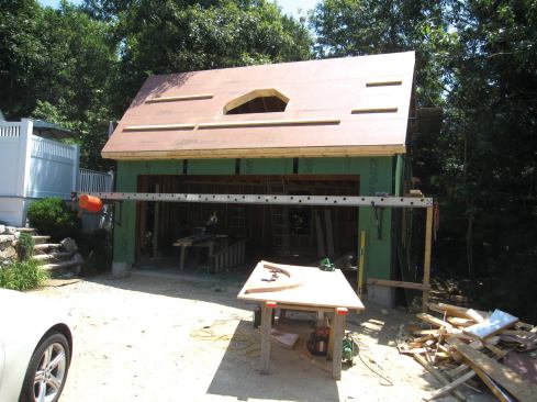
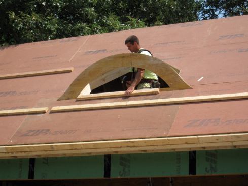
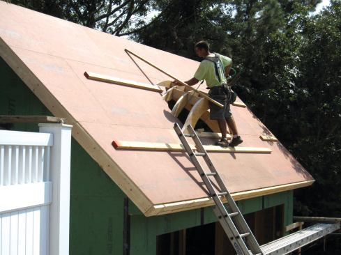
With all the patterns in hand, I turned the process over to the able hands of the carpenter, Ryan Dangelo. He and his dad, Mike, of M.J. Dangelo Construction, in Centerville, Mass., framed the garage walls and roof, headering off a rectangular opening in the roof with the upper corners angled in. To frame the dormer, Ryan cut the ribs out of the 24-inch-wide LVL. He taped the printed patterns onto the face of the LVL and cut the curves with a jigsaw. The first rib, at 27 1/4 inches, was too large to be cut from one piece, so he cut a separate sliver from the window cut-out material and then attached it to the top of rib before it was installed.
So that the ribs would sit plumb on the 12/12 pitch of the garage roof, Ryan angled their bottom edges (where they attached to the roof), using a circular saw with the blade set at 45 degrees. The entire bottom edge of the first rib was angled, but just the ends of the next two ribs were angled. Those lines were spelled out clearly on the printed pattern. The uppermost rib bore fully on the roof so it, too, was angled across the entire bottom edge.
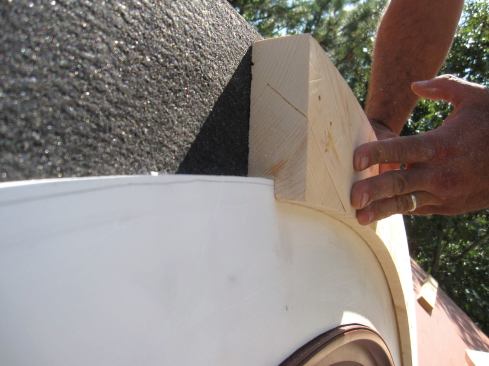
Before installing the first rib, Ryan cut a 45-degree angle along a length of 2×4 and tacked it to the roof to hold the rib in position for nailing. When the rib was centered properly on the opening, he nailed the rib through the roof sheathing and into the framing below. He plumbed the rib and then tacked a furring strip from the rib to the roof above to hold it in position.
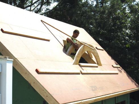
Ryan used spacer blocks to position the rest of the ribs. He made the blocks the proper length to space the ribs 10 1/2 inches on-center, cutting the ends of the 2×6 stock at the plumb angle for a 4/12 pitch. Three spacers (a top block and two side blocks) were used to space the second and third ribs. To position the small top rib, he used a single top spacer cut from a 2×4.
Cut & Layer the Trim
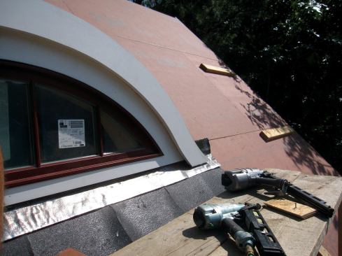
With the frame complete, the next step was weatherproofing and installing the window. Ryan started by wrapping heavy felt paper from the face of the dormer down onto the roof. The felt paper would be woven into the roofing underlayment below the dormer. Next he angled a length of lead flashing that wrapped over the bottom of the window opening of the first rib to act as pan flashing. The lead flashing extended down onto the garage roof about 4 inches. The window finally went in with the curved flange caulked to the rib opening before it was nailed. The final layer was peel-and-stick membrane that covered the rib and lapped down over the flange as well as over the lead flashing on the sides of the window.
The trim around the window was done in a total of four layers. Because of the relatively small area around the window on the face of the dormer, I opted to make the window trim from a single piece of 3/4-inch-thick cellular PVC with an opening for the window cut out of it. The subfascia was the next layer, followed by two layers of fascia trim.
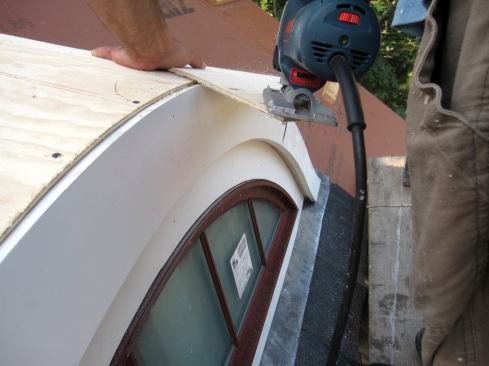
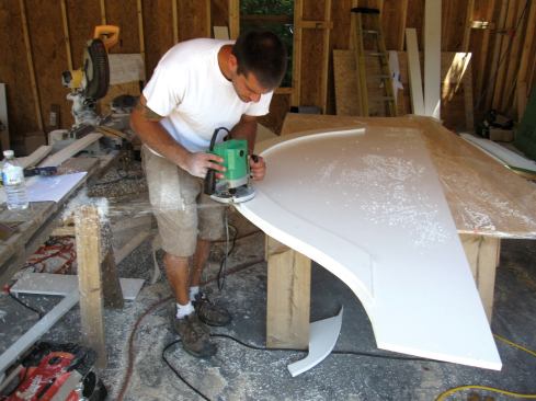
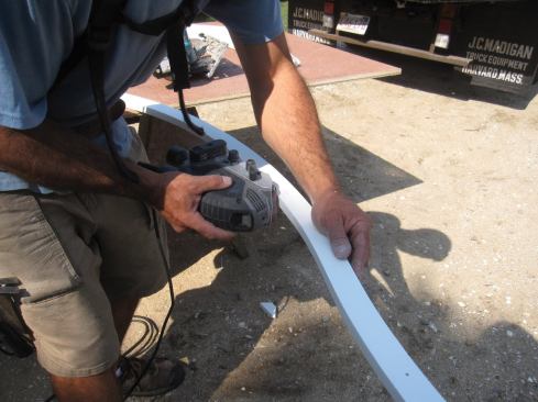
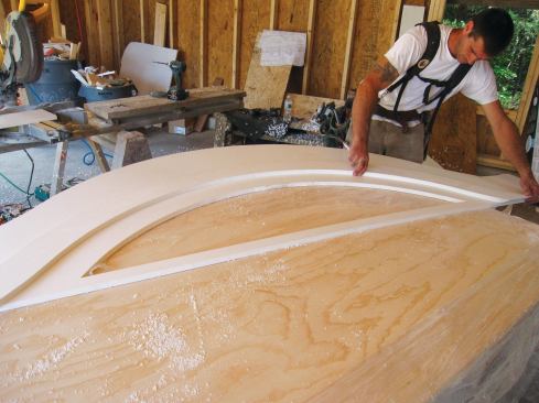
For the finish trim, Ryan first cut the outer layers of fascia trim that shared the identical outside curve. To lay out these pieces, he cut out the individual patterns from the printout I’d given him and taped the cutouts to the sheet of PVC. He started with the wider fascia trim, cutting the curve and then smoothing it with a small belt sander. When he’d finished with that piece, he tacked it back onto the sheet of PVC next to the curve he’d just cut. He then used the outer edge of that piece as a template to cut the curve for the second layer of fascia trim. To make the cut, Ryan mounted a flush-trim bit with an upper guide bearing in a heavy-duty plunge router. With the bearing riding on the curved edge of the first piece of fascia trim, he was able to quickly and easily cut the curve for the second piece. Then it was just a matter of cutting the second piece to width and smoothing the inside curve with a belt sander.
The window trim layer was cut out of the rest of the sheet of PVC, again by cutting out the pattern and taping it to the sheet. After dry-fitting all the trim on the ground, he nailed the window trim layer into place.
The subfascia was the last trim layer to cut out, and I’d laid it out to be cut in two pieces that would meet at the top of the eyebrow. Strength was not a concern with the subfascia, so I opted for dimensional lumber for this layer. Ryan cut out the patterns from the printout, taped them to a length of 2×12, and then cut out the pieces with a jigsaw. The subfascia needed to lap over the window trim, so he routed a rabbet in the lower edge of the two sections. He then nailed on the subfascia and the first layer of fascia trim. The fascia layers extended past the window trim with space left below for the shingles. The final layer of fascia trim went in after the roof was sheathed.
Sheathe the Curved Shape
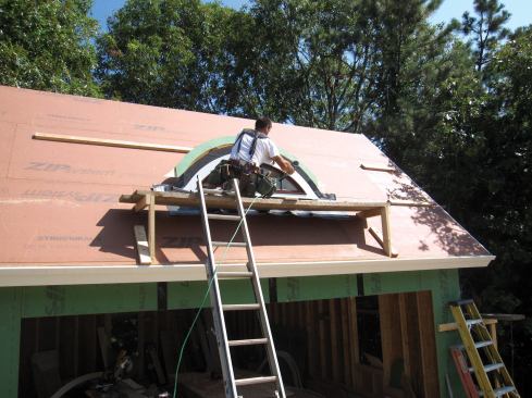
For the roof sheathing, Ryan laid the patterns out on sheets of 1/4-inch plywood and cut them out with a jigsaw. Because the circumference of the dormer roof was more than 8 feet at its widest, each layer of sheathing had to be pieced in at the front corners.
The pieces fit quite well directly from the pattern, although Ryan did some minor tweaking with a jigsaw to get them to sit just right. He screwed and glued the first layer to the ribs, starting in the middle and working to each side. Then the second layer was screwed and glued to the first.
After the sheathing was in place, the final piece of fascia trim was installed with the top edge flush with the top of the sheathing. Asphalt shingles were installed on the garage roof up to the front of the dormer. Then multiple layers of roll roofing were put on the dormer, lapping across the valley and onto the garage roof. Ryan ran red-cedar shingles as a starter course on the dormer and then wove asphalt shingles across the valleys. The shingle installation was almost more complex than building the rest of the dormer. Getting the shingles to lie flat across the curved valleys took a bit of finesse.
Although this dormer did not require a finished interior, it could easily have been finished as constructed, or the ribs could have been extended down between the doubled rafters on the garage roof to form the interior ceiling. In the end, the eyebrow dormer was an elegant addition to a simple garage structure, and it has drawn many compliments from people passing by.
See more illustrations and photos on my website.