Tim Uhler
On the houses we frame, we often add a “hip tray vaulted ceiling” in the master bedroom, hallways, or other rooms where we want to add inexpensive architectural drama. Over the years, we’ve refined an efficient and easy method for framing them (see “Framing a Hipped Tray Ceiling,” JLC, May/06).
We recently had a master bathroom where we decided to frame the tray ceiling octagonally rather than as a rectangle. We chose this layout because the room had one 45° wall, and with a simple hip tray, the ceiling corner would have awkwardly died into the angled wall. But with the octagonal layout, the soffit mirrored the 45° angle instead. We use this same layout method for turret roofs as well.
Soffit framing. The first step is to frame out the perimeter soffit. We often have 2×12 scraps left over from cutting and stacking a roof, and we save any pieces that are long enough to frame out these ceiling soffits. We typically frame them to be either 18 or 24 inches wide. This room was on the smaller side—about 10×12 feet—and 18 inches worked well. For a normal master bedroom—12×16 feet or larger—we would frame 24-inch soffits.
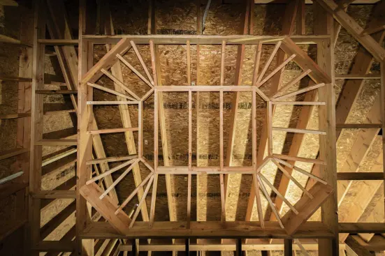
On a master bathroom project, the author decided to frame the tray ceiling octagonally rather than as a rectangle.
To keep the soffit straight, we run a string and fill in with cripple blocks to the ceiling rafters as needed to push the soffit in line. After the soffit is boxed in, we “45” the corners, making a 24-inch diagonal at each inside corner. Once this is done, we snap a line 5 inches up from the bottom of the soffit all the way around. The bottom edge of the rafters will fall on this line, leaving a fascia for crown and for lighting, if the customer chooses.
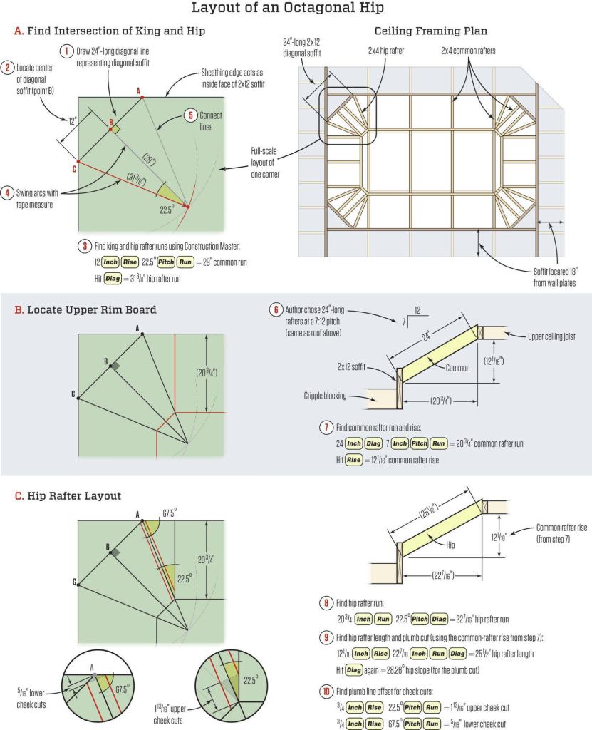
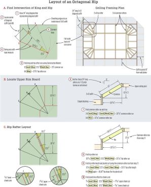
Full-scale drawing. I like to grab a piece of sheathing and lay out one corner of the ceiling at full scale, so I can write down the numbers I need for all my calculations.
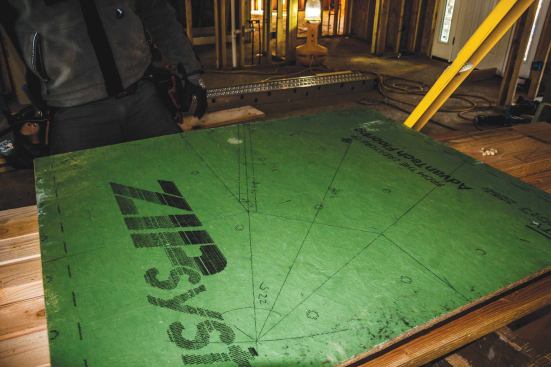
The author likes to use a piece of sheathing to lay out one corner of the ceiling at full scale, then write down the numbers needed for all of his subsequent calculations.
I do all the layout on this piece of sheathing, using its edges as the inside face of the 2×12 soffit, and drawing a diagonal across the corner to define the 67.5° corners where the hips will be nailed. A regular hip splits a 90° corner (making 45° angles); an octagonal hip then splits the 45° angle, making 22.5° angles between the hip and the commons on either side of it.
I start the layout by finding dead center of the diagonal corners of the soffit (12 inches on this particular ceiling). Drawing “A” shows the calculations that I make using my Construction Master calculator to lay out a full-scale section of one corner.
Tim Healey
Upper ceiling plane. Once this section is drawn, I draw where my upper ceiling line will be. I like to work in round numbers, so for this size room I chose a 24-inch-long rafter at the same 7:12 pitch as the roof above. (To draw attention to the ceiling in a larger room, I might use a 36-inch-long rafter and steepen the pitch, but in this small room, that wasn’t necessary.) Drawing “B” shows the layout and calculations needed to draw the upper ceiling line on the full-scale drawing.
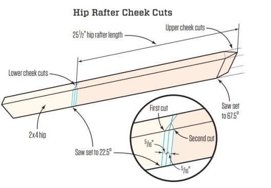
Hip-rafter layout. Next, I lay out the hip rafter, as shown in drawing “C” . This allows me to draw the actual thickness of the hip (2-by) and the common, so I can just measure off my adjustments to get my cheek cuts laid out, as shown in the illustration above.
Cutting rafters. I can now cut eight hips (two per corner) and all the commons. To cut the hips, I use the Big Foot 10-inch saw with a swing table. This base plate will bevel to 75°, so it can handle the 67.5° bevels needed for the upper hip cheek cuts.

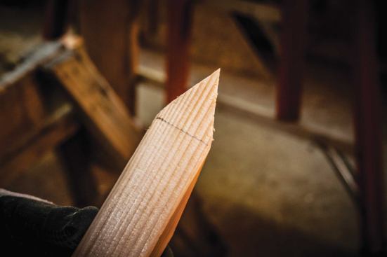
The author cuts the steep cheek cuts first (left photo). Then he pulls the length and layout, and makes the lower cheek cuts (above).
Tim Healey
28.26° hip slope (for the plumb cut).
I like to cut the steep cheek cuts first, then pull the length and layout, and cut the lower cheek cuts. For the lower cuts, I square the length to the side of the rafter and draw a plumb line. Then I measure the setbacks (5/16 inch) on both sides of this first plumb line, giving me three parallel plumb lines. I cut on the “long” line first, with the blade angled back toward the rafter; then I cut the “short” line from the other direction, giving me the double cheek cut.
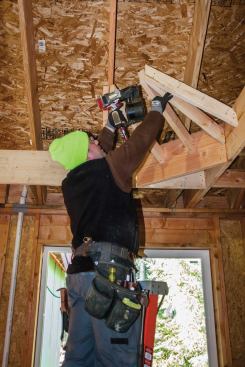
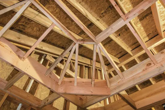
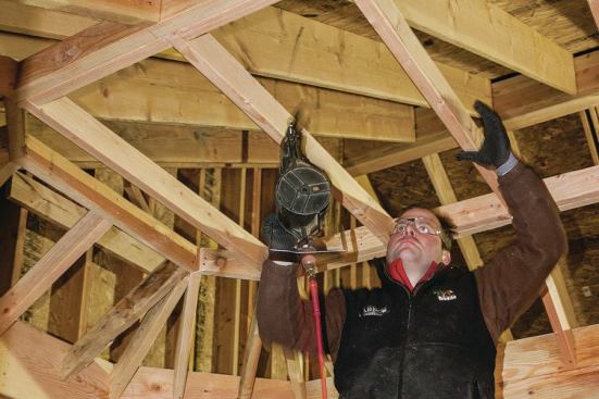
After making the cuts, the author begins the framing in the corners, installing the two commons and one hip (left photo). Then he fills in the common rafter framing (above).
I like to frame all my corners (two commons and one hip), then fill in the common rafter framing. Once that is finished, I measure in the upper ceiling framing and nail it off, making sure it’s strong enough to hang from and that there will be no ceiling joists in the way of the light placement.
Photos by Tim Uhler.


