Load Path
A building’s load path starts at the roof and transfers vertically through the framing to the foundation. A simple load path example when trusses and studs line up with each other and bear directly on the foundation, as shown in the photo below.
Depending on the wind zone or other structural requirements, framing connectors may be needed to strengthen these aligned connections. Metal connectors, such as those shown in the image below, can may be required to help transfer loads when framing members do not perfectly align.
If the loads are not transferred properly, you end up with cracking of interior finishes or sagging framing. Many cracking problems due to “settling” are actually due to what is commonly referred to as “broken load paths” – paths that put loads on areas not meant to carry them. In seismic and high-wind zones, the consequences of broken load paths can result in complete devastation of the building. This is one of the most common framing errors and an area of concern that will likely be scrutinized by building code inspectors.
Joist Hangers
Joist Hanger Fasteners
Fastener choice is one of the most common mistakes with wood framing connectors.
- The required fastener type is usually stamped on the connector. Do not substitute: Using a nail with a different diameter, length, or steel type can reduce shear capacity.
- When using screws, use only those specified by the manufacturer. Do not use deck or other screws: they are too brittle.
- For connectors that require the use of bolts, drill a hole no more than 1/16 in. diameter wider than the bolt. Larger holes will compromise the strength of the wood.
Why the Different Shaped Nail Holes?
Wood I-Joist Hangers
Wood I-joists require special hangers. Do not try to adapt conventional hangers.
I-Joist Hanger Height
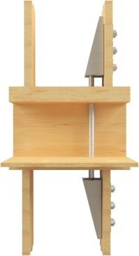
Hangers for wood I-joists should be tall enough to catch the I-joist’s top flange unless a web stiffener is used; otherwise, the joist may roll in the hanger (I-Joist Hanger Height, below). If a web stiffener is used, the hanger side flange should be at least 60% of the joist depth.
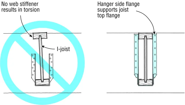
Joist hangers must be the full height of the I-joist (right), unless web stiffeners are used. Otherwise the joist may twist (left).
I-Joist Hanger Width
Hangers for wood I-joists should be the same width as the joist flange. Do not trim the flange to fit a narrower hanger; this would reduce the joist’s strength. A wider hanger will either leave a gap, potentially causing a squeak, or will require filling with plywood, which would unevenly load
the hanger.
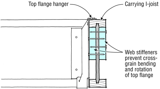
Before installing hangers to an I-joist, install web stiffeners against the bottom of the top flange of the carrying joist so that every nail in the hanger can be filled.
Nailing I-Joist Hangers
Nail in every hole with correct sized nails; leaving nails out greatly reduces the hanger’s capacity. Nails that are too long can hit the bottom of the hanger and curl under the joist, causing a squeak.
Web Stiffeners
For I-joist to I-joist connections, install web stiffeners against the bottom of the top flange of the carrying joist (Hangers on I-Joists, above).
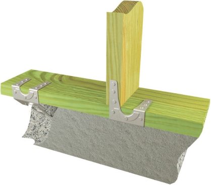
Wood Nailers for I-Joists
For hangers that bear on wood nailers, the nailer should not overhang its support more than 1/4 in. or sit more than 1/8 in. in from the edge (I-Joist Hangers on Concrete and Steel, below).
Using Connectors to Resist Shear
When wind pushes a house or an earthquake shakes it, the force is delivered to the top of the shear wall. At the bottom, where the wall is attached, there is an equal resisting force in the opposite direction. The “overturning moment” (a moment is a force times a distance) equals the force at the top of the wall times the height of the wall.
In a shear-wall assembly, the resisting force is provided by the hold-downs that achor a “tension post” on one side of the shear assembly, and a “compression post” on the other side. For the shear wall to work, hold-downs must be correctly sized to handle the tension force generated. They must also be installed correctly so they can adequately transfer the forces to other parts of the building.
There are a range of different hold-down connectors available:
USP
Depending on the load, a face-nailed hold-down that simply connects studs in a sheathed wall to the bottom plate may be sufficient.
USP
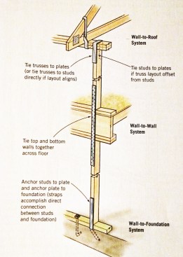
In seismic and high-wind zones, hold-downs that connect the tension and compression posts in a shear-wall assembly to the foundation (left) may be required, or hold-downs that transfer shear forces between floors (right).

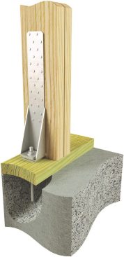
Proper Installation
Assuming the anchor bolt is properly embedded, this hold-down is correctly installed.

Hold-Downs Won’t Compensate for Bad Wall Detailing
It’s a mistake to attach two hold-downs to a single post. The two shear walls meeting at this corner should have been properly connected with nails, and one correctly sized hold-down attached.

Short Wall, Notched Plate
This shear wall is not long enough (plate length) to meet code, and the plate has been so badly mangled by the HVAC sub that its lateral strength is compromised.

Poor Tension Strength
The window opening at the bottom left of the photo was enlarged, pushing the first-story hold-down post out of line with the second-story post. In a quake, the uplift forces will likely rip the long threaded rod through the header or pull the header out of position.
Using Connectors to Resist Uplift
When high winds strike a house, the flow of air over the roof creates an upward suction, in the same way that wind creates lift on an airplane wing. If any connection anywhere along that load path fails, the structure can be pulled apart.
The two basic ways to resist uplift are:
- Steel connectors.
- Plywood or OSB wall sheathing, carefully applied and heavily nailed in a way that lets the sheathing and nails pick up much of the uplift load. In this case, connectors still need to be used in certain areas.
The drawings here focus on the use of connectors. For the plywood approach, the publication Design for Wind Resistance from the APA: Engineered Wood Assoc.
Uplift load path. In considering uplift, engineers estimate the upward pull on each connection, from the roof sheathing to the foundation, and specify appropriate connectors and nailed sheathing.
Load Path Around Wall Openings
Where plywood or OSB sheathing is relied on to resist uplift, window and door openings will still need load-rated steel connectors – at the base of the window jacks, at the points where headers rest on jack studs, and between the headers and the framing above them.
Wall-to-Wall Connections
In two-story houses, uplift loads from an upper story to a lower story can be transmitted across the second-floor frame with steel straps. Plywood or OSB sheathing that spans across the floor system can also serve the purpose, but all edges must be nailed to solid framing or blocking. Guidance on sheathing-based techniques to resist uplift can be found in APA Publication E510 (available with registration from APA: The Engineered Wood Assoc.).
Preventing Plate Twisting Problems
Truss or rafter ties should tie the roof directly to the studs in line with uplift straps, not just to the wall plate (left). If the connectors simply tie the inside of the wall plate to the roof framing, the plate can twist under a load, reducing the strength of the connection (right).
For information on retrofit uplift connections, see Strengthening Roof-to-Wall Connections.
Common Errors with Framing Connectors
Installation errors can affect the load capacity of framing connectors and — if not corrected — cause long-term problems, such as cracking and separation of finishes or failure in weather or seismic events. Here are some of the most common problems and how to avoid them.
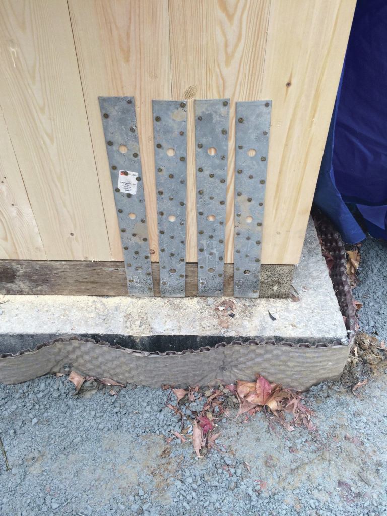
Misplaced Anchor Bolts
In seismic regions, codes typically require that foundation bolts have 3-inch-square bearing plates instead of washers. An incorrectly placed bolt can cause the bearing plate to extend beyond the edge of the sill or to conflict with the framing, as shown to the left.
Do not notch the stud. Instead, use a slotted plate, such as the one shown in the photo to the left, which can be offset to accommodate an anchor bolt near a stud.
Another way to reduce framing conflicts is to use strap anchors instead of bolts.
Spalling at Embedded Straps
If a hold-down is wet-set or bent while the concrete is still green, it can cause spalling in the concrete. Spalls less than an inch tall will not affect the hold down’s load capacity, but those between 1 and 4 inches will reduce capacity by 10 percent and should be checked by the engineer or designer. If spalling is severe, you may be able to retrofit the connection with an epoxied threaded rod or mechanical anchor, code permitting.
Excessive Bends in Strap-Tie Offsets
Strap-tie hold downs installed over the sheathing may need to be bent horizontally, but the offset should not exceed 5/8 inch. Easing or lightly notching the panel edge, and nailing from the bottom of the strap upward will prevent the strap from bulging and keep wall movement to a minimum. More than one 90-degree bend is not allowed.
Hold-Down Bolts Too Short
When an anchor bolt is set too low in the concrete, there may not be enough exposed thread to properly connect the hold down. To achieve full strength the bolt must, at a minimum, be flush with the top of the tightened nut.
Anchor Bolt Misaligned For a Hold Down
If a bolt is too far away from the framing it can sometimes be salvaged by extending it with a coupling nut, then gradually offsetting it to meet the raised hold down. As a general rule the rod should be within 5 degrees of plumb, or no more than a 1/4-inch of offset for every 3 inches of additional height. However it’s best to check with the hold down manufacturer.
Missed Holes
A gun-driven nail that misses the factory-punched hole and makes its own reduces the connector’s shear capacity. Framing connectors should not be installed with a regular framing nailer, but rather with a specialty nailer that advances the nail first so it can be registered in the hole before firing the trigger.
Overdriven Pneumatic Nails
Overdriven fasteners cause excessive dimpling and weaken the hardware by fracturing the steel around the nail hole. The solution is to use a specialty framing-connector nailer that allows you to properly set the driving depth.


