When architect Eric Sokol (Winkelmann Architecture, Portland, Maine) took on the task of squeezing a high-end custom home into the pie-shaped buildable outline of a lakeside lot in the Maine woods, he solved the problem using every trick in the book.
Stairs from a split-level entry on the road lead down to a wide-open living and entertainment space with exposed wood ceiling beams. Upstairs, a pair of shed-roofed spaces set at a 10-degree angle to one another, and connected by a flat-roofed passageway, form the shell for a master bedroom suite at one end of the house and an open-plan living, dining, and kitchen area at the other end.
To frame the custom forms, architect Sokol and engineer Albert Putnam specified a smorgasbord of structural components tailored to manage the long spans and point loads involved: steel I-beams, heavy glue-laminated timbers, built-up laminated veneer lumber (LVL) girders, custom angled steel connectors, trimmable-end web-truss floor joists, and wood I-joist roof rafters.
Sokol and Putnam’s complex assembly posed a construction challenge to Maine builder Jesper Kruse, owner of Maine Passive House, and his crew of skilled carpenters. Over the winter, JLC spent several days on the jobsite with the Maine Passive House team to see how they put the puzzle together.
Steel and Timbers
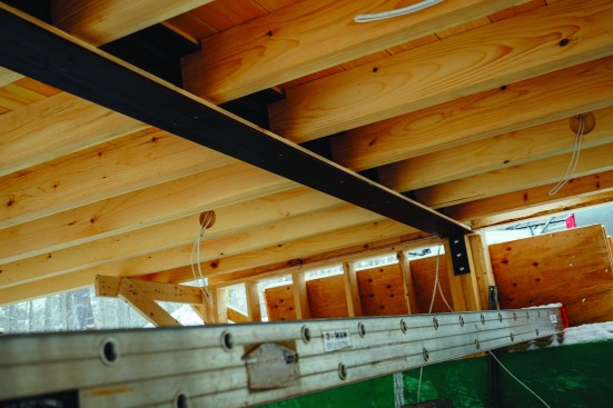
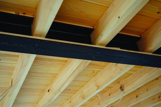
The basement room will get a polished concrete floor. Overhead, its ceiling is exposed wood: tongue-and-groove 1×6 pine boards laid over sawn 3×8 pine joists, supported by a flush steel beam. It’s Sokol’s trademark style, and Kruse has built it before.
Sokol likes the rugged look of the exposed steel beam and sawn rafters. Beyond that, building height restrictions constrained the head height in the lower-floor room, and the exposed beams add a feeling of greater height to the ceiling.
Regardless of the aesthetic considerations, said engineer Putnam, the stiffness of steel made the I-beam the only practical choice to support the ends of the sawn joists and allow a clear span across the room. Engineered lumber could have carried the load but would have required too deep a member. “The stiffness of steel (its modulus of elasticity) is 29,” said Putnam. “The stiffness of LVL is 2. An LVL that would carry the load would have had to be 16 inches deep or more, not 8. You couldn’t make it flush to the ceiling.”
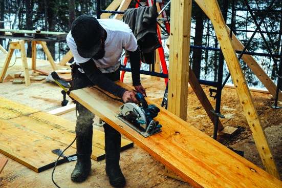
Sokol’s plans included light fixtures routed into the sides of the pine ceiling beams and supplied by wiring running in grooves routed into the tops of the beams. Sokol made the framing task easier for Kruse’s team by providing detailed drawings. Kruse turned to Rusty Partridge (blackdogtimberworks.com), a local timber framer, to supply the sawn floor joists.
Timber framer Rusty Partridge supplied precut timbers, routed out for wiring chases and electrical boxes.
A stiff mid-span steel beam was integral.
The steel beam helped achieve the required span.
After nailing down tongue-and-groove ceiling boards topped by AdvanTech subflooring, the crew locked the joists in from below with pan-head screws.
“Rusty routed out the wiring chases in the tops of the beams and the holes for the electrical boxes to sit inside the beams,” said Kruse. Sokol had also specified exact locations for screw holes in the lower flange of the steel member for fastening the sawn joists, said Kruse. “So they drilled those holes at the steel shop, and then Rusty went down to the shop and cleaned up the steel beams and coated them with beeswax. And he brought them up to the site, and he brought his Bobcat with a boom to set the steel beams.”
The sawn joists rest on a ledger of 3/4-inch pine set on the lower flange of the I-beam. Kruse’s crew pinned that ledger in place with short temporary screws, then set the sawn beams in place by hand based on Sokol’s layout. Then, after the pine ceiling and upper-story subfloor were in place, the crew backed out the small screws and replaced them with long pan-head screws extending into the sawn timbers. “We wanted the screws to look good with the steel beam, so we took a torch and burned the coating off the heads to expose the metal,” said Kruse.
When the Ceiling Is the Floor
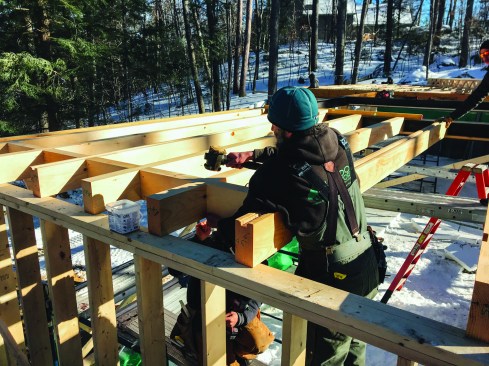
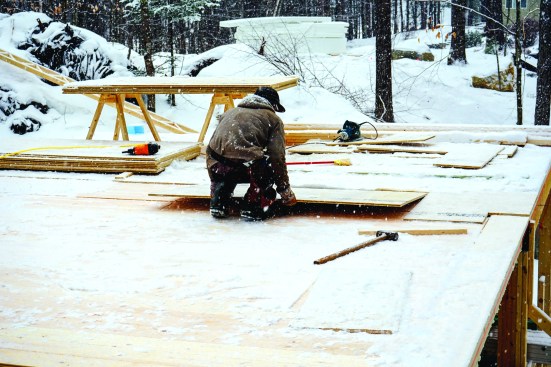
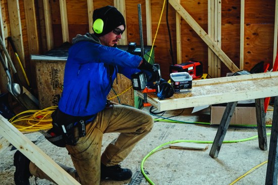
The design called for building the lower story’s ceiling into the upper story’s subfloor. This required Kruse’s crew to glue and nail the pine boards to the wood timbers. At the same time, the crew had to install and protect the rough wiring for the lower room’s ceiling lighting fixtures. Working from both sides of the steel beam, the carpenters laid out their starting courses for the tongue-and-groove pine so that the edges of the final courses would fall short of the center of the steel beam, leaving access to wiring runs on top of the steel. To protect runs of wiring set into the channels along the tops of the sawn joists, the crew laid strips of steel into the grooves before nailing down the pine boards.
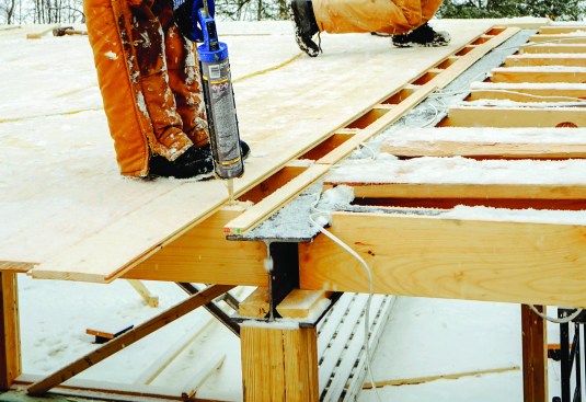
Working in a light snowstorm, the crew glued and nailed tongue-and-groove pine boards to the sawn beam framing.
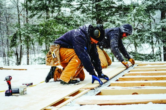
They took care to leave space for wiring that serves light fixtures in the room below.
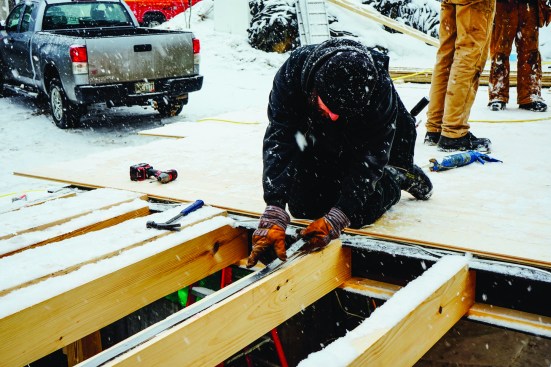
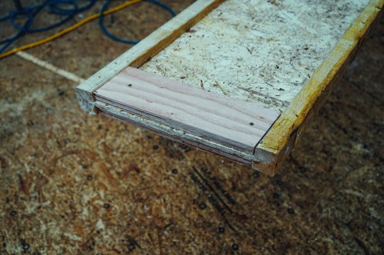
The wiring chases were capped with steel to protect the wires.
Then the crew covered the whole layer of boards with a top course of AdvanTech subflooring.
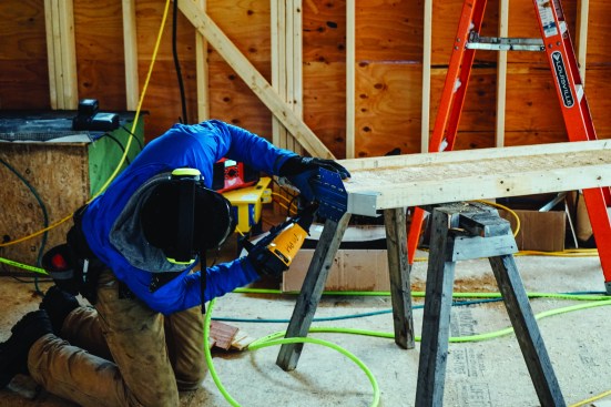
After all the boards were in place, the crew glued and nailed 7/8-inch AdvanTech subflooring panels over the pine, taking care to nail only into the beams. They snapped chalk lines on the subflooring to mark the edges of all the beams that housed wiring runs, and used screws to fasten down the AdvanTech at those locations, to remove the risk of a nail near the edge going astray and either hitting a wire or shining out on the ceiling below.
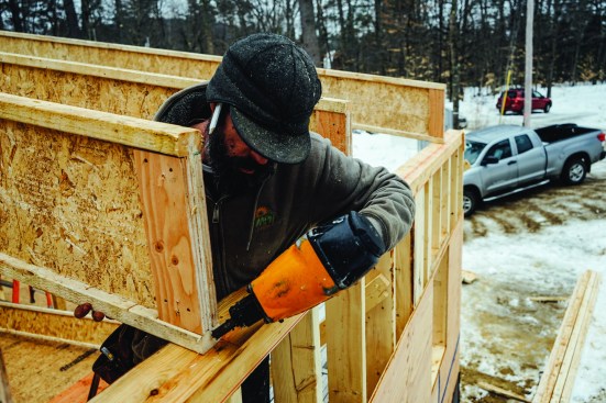
Carpenters Alex Strugatskiy and Will Kessler framed in the window opening between two large glulam carrying beams with 2×6 lumber. Strugatskiy laid out stud locations.
Glulam Headers
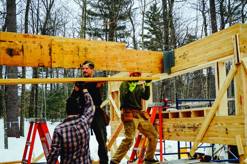
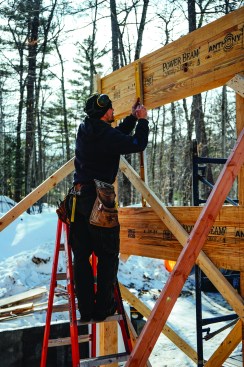
At the front of the house, a flat-roofed entry greets the street, with wide windows looking out onto the road. A structural header across the uppermost window has to do more than just hold up the entry roof, however. It also receives the end of a huge, triple-LVL built-up beam that extends through the width of the house from front to back (see photo, top of page), supporting one end of the long living-room roof—and also helping to hold up the flat-roofed center section of the building.
We see the crew assembling that massive LVL in place in the next two pages. But first, they had to build the front wall to support its end. “The engineer gave us a choice for the header,” said Jesper Kruse: “A glulam or a built-up LVL.”
“It varies by contractor,” said Putnam. “Some folks like to use individual plies, at an inch and 3/4, because they can more easily handle it. But in that particular connection, there’s a lot of load that needs to move through that heavy-duty Simpson girder hanger. It’s a side-loaded flush connection. And if you are connecting a huge side load through three plies of LVL, 33% of that load needs to get to the furthest ply away from the hanger. So if you use LVL, you need to add a bunch of bolts to the connection.”
They boxed out the window opening.
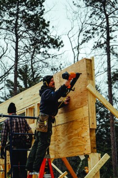
Then they nailed plywood sheathing onto the face of the wall to stiffen the structure.
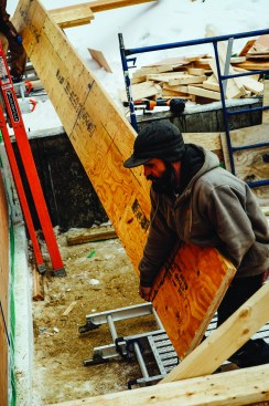
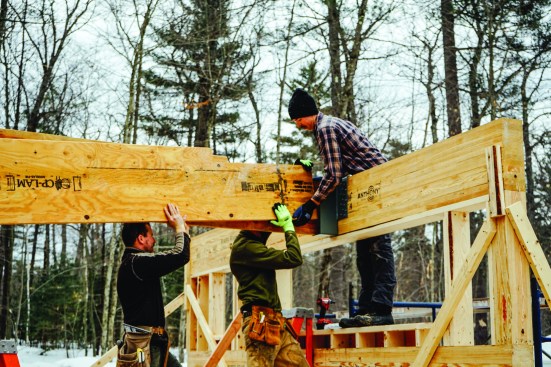
“So we said, ‘Let’s go with the solid piece,’” said Kruse. “If it had been up high like the other beam, we might have had to use LVLs and bolt it together. But with that lower one, it wasn’t too hard to lift the glulam up. We lifted one end up onto the scaffolding, and then the other end, very carefully. We were seven guys doing it, and it was manageable.”
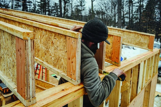
The front wall actually has two glulams: one above the window to support the flat roof of the center of the house, and one below the window to support an entryway and garage roof. Before attaching the huge Simpson hanger to the face of the top glulam, the crew framed in the window opening between the two glulams and sheathed the wall to stiffen it (see photos, facing page).
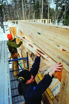
Engineered LVL material lets carpenters assemble high-capacity beams on site, using manageable pieces with uniform strength characteristics. Carpenter Matt Friel helped carry 28-foot pieces onto the home’s floor deck.
A Built-Up LVL Beam
With the glulam header wall in place, the crew set about cutting and assembling the big LVL beam that would tie into it. Although the LVL plies were 28 feet long and 20 inches wide, two carpenters could wrestle the pieces off the lumber pile and move them around to the deck for cutting to length.
At just 1 3/4 inches thick, the LVL plies were a convenient size for cutting and fastening with ordinary framing tools. To cut the beams to length, lead carpenter Matt Friel took his measurements from Sokol’s plans and checked them against the actual measurement from the post he had just set at the back of the house that would hold up the far end of the beam. Then he measured and marked each ply, using a 4-foot drywall square to mark his lines.
Making things even more interesting, Sokol’s design oriented the home’s two wings at a 10-degree angle to each other (part of fitting the building to the property’s tightly constrained buildable area). So the site-built LVL beam, which would help carry roof loads for one shed-roofed wing and the flat-roofed center section, would need to join its supporting glulam at the same 10-degree angle.
For $450, Simpson Strong-Tie supplied an EGQ high-capacity beam hanger fabricated at the required angle (the EGQ can be sloped and skewed as much as 45 degrees, according to Simpson). It was up to the carpenters, though, to make the correct angle on the beam end. Friel had to start with the longest angle cut, then subtract a fraction for each cut on the next two pieces of LVL.
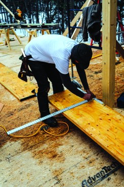
Cut lines were marked with a 4-foot square.
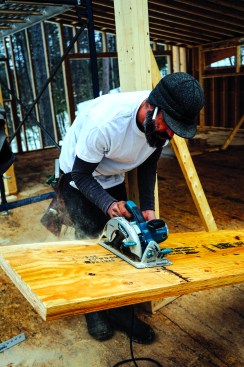
Then the pieces were cut to length at the architect-specified 10-degree angle.
That’s not all. The flat roof of the center section of the building was to be framed with 16-inch wood I-joists, and Sokol’s design originally called for the big LVL girder to also be 16 inches deep—which would match up perfectly with the flat-roof rafters. When engineer Putnam checked the plans, though, he found that a three-banger 16-inch LVL would deflect too much in the center where it crossed the open kitchen. So Putnam bumped the beam size up to 20 inches.
But at 20 inches deep, the LVL would be too high for the flat-roofed portion near the road—the beam would stick up above the roof. So Friel had to notch the end of the beam down to 16 inches.
You have to be careful when you notch a beam, Putnam said. Engineers commonly check beams for three qualities: strength in bending, deflection, and shear. Bending strength and deflection are the main concerns at the center of the beam, but shear sometimes becomes important at beam ends. In this case, Putnam found that the 20-inch depth was necessary at the center of the span, where deflection controlled the analysis, but not at the ends. So a 16-inch depth would suffice for the short section where the flat roof would join the beam. That’s only because the notch was at the top of the beam, Putnam pointed out; if the carpenters had needed to thin out the bottom of the beam instead, they would have introduced a risk of splitting at the notch.
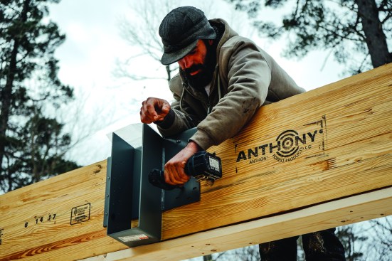
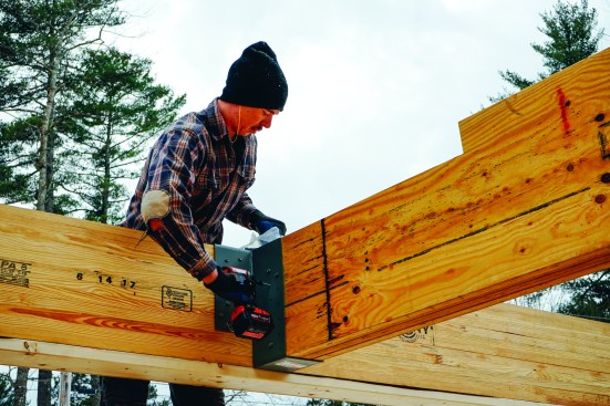
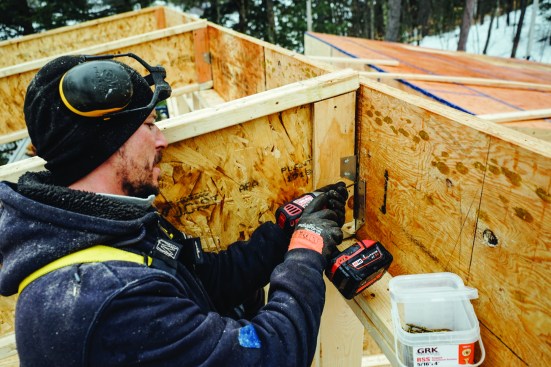
Matt Friel attached the Simpson beam hanger in position with Simpson SDS screws.
He laid out and cut a notch on the end of the beam to match the framing of the flat-roofed section at the front of the house.
Friel set the big Simpson hanger in position using the supplied Strong-Drive SDS structural screws, taking care to put a screw in each hole. Next, he cut down the end of each LVL beam ply to 16 inches deep. Then it was time to assemble the beam; the crew lifted the long pieces into place one by one, screwing them together along their length with structural screws, and finally screwing the completed beam into its hanger with the Simpson-supplied fasteners.
Then the crew muscled the LVL pieces into place one by one.
Once in place, the beam is secured to the hanger with screws.
Carpenters know that wood can be an inconsistent material that warps, shrinks, and twists. Engineered lumber is more consistent, but even LVLs aren’t perfect. In this case, one piece of LVL showed a noticeable cup across its width. The crew had to screw the plies together in the center first, then persuade the cupped ply to lie flat at the edges using clamps and more screws.
A Wood I-Joist Shed Roof
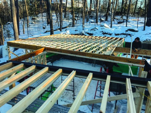
The upper-story living-dining-kitchen area is designed as a single open-plan space with a high ceiling. Eventually, this room will get the same ceiling treatment as downstairs, with sawn wood rafters and a center-span steel beam. The sawn rafters won’t be structural (they’re for looks only), but the steel beam at mid-span will be real; it will help support the wood I-joist shed roof.
Without the mid-span steel beam, engineer Putnam told JLC, the 16-inch-deep wood I-joists might struggle to make the room’s 28-foot span. “The snow load at that location is about 70 pounds per square foot,” Putnam remarked. “You can expect 3 feet of snow in winter.” With the steel beam cutting the span in half, however, the wood I-joists are comfortably oversized. “The rafter depth is just there for insulation thickness,” said Putnam.
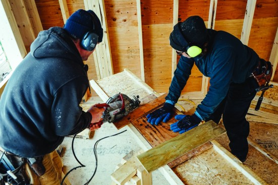
Jesper Kruse and carpenter Anna Heath made rafter plumb cuts using a site-built jig.
Carpenter Ryan Bielenda packed out each rafter web with plywood stiffeners.
Kruse planned to insert the steel beam later. For now, the crew just needed to set the long wood I-joist rafters. They started by cutting the pieces to length, using a site-built jig that guides the circular saw at the correct angle and allows the saw to ride across the rafter’s web without falling in. “It makes it easy,” said Kruse. “You just line the jig up in the right place, and it’s one nice cut across.”
Then he pre-applied Simpson adjustable wood I-joist hangers, which can be adjusted in the field to the necessary angle for a sloped or skewed connection.
Then the crew packed each rafter out with plywood web stiffeners. These help transfer loads from the top flange of the member down through the web, and they also provide nailing for metal connectors. Before passing the rafters up to carpenters at the wall plates, the crew on the deck attached metal connectors to the rafter ends.
Setting Rafters
The crew had angled the top cuts on the studs for the wall that supports the lower end of this long roof span, creating a beveled top plate for the wall, so that the wood I-joists could sit flat on the plate. At the top, where the rafters dead-end into the LVL rim joist (which is also the window header), the wood I-joists were fastened using angled Simpson LSSUI joist hangers.
The roof assembly includes load-bearing LVL rim joists that span over windows in the end walls. Matt Friel measured from the edge of the beveled bottom plate to allow room for the LVL.
The rafters were nailed into place.
“I like the way Eric used the LVL band joists to do the work of the window header in a bunch of places,” said Kruse. The crew did have to take care that rafter ends falling above window openings were attached with load-bearing metal connectors. But the method saved labor and reduced the amount of thermal bridging in the wall. “When we use engineered wood band joists at the floor perimeter in a two-story wall,” Kruse said, “we like to hold the wood back from the edge of the plate and put some rigid foam in there for a thermal break. You just have to make sure your sheathing spans across the foam from the lower wall to the upper wall. But at the top of the roof like this, we would rather have solid lumber behind the plywood for attaching eave overhangs and trim.”
Alex Strugatskiy fastened the skewed connectors to the LVL at the top.
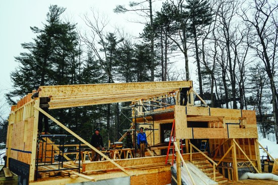
The building began to take shape.
Complex as this unique custom job was, Kruse and his crew made good time. “I have a really good group of carpenters right now,” Kruse said—and he also gives architect Eric Sokol part of the credit. “Sometimes you get plans from an architect, and they didn’t think about this and they didn’t think about that,” said Kruse. “That happens just about never with Eric. At first, it’s hard to see how it’s all going to come together. You get the plans and for a long time, you’re just looking at it and trying to figure out what the heck it is. But then eventually it clicks.”
Photos by Ted Cushman and Jesper Kruse


