As a HERS rater and Passive House consultant working for a professional home performance and insulation contractor, I see all kinds of houses, from old-school energy hogs built in the 1960s and 1970s to award-winning high-performance homes built recently with the latest materials and methods.
Some of the builders in our market are struggling to meet our most recent energy code’s benchmarks, using house designs that date back to the 1970s and 1980s. Sometimes, the framing systems from those older house styles are a stumbling block. Scissors trusses can be an example of that problem—but they don’t have to be. With a few thoughtful modifications, a scissors-truss roof system can contribute to outstanding energy efficiency.
In this story, I’ll show some tricks for squeezing better performance out of conventional old-school scissors-truss roofs. Then I’ll take a look at the improved version of a scissors truss that our company has used to build exemplary high-performance homes.
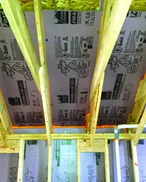
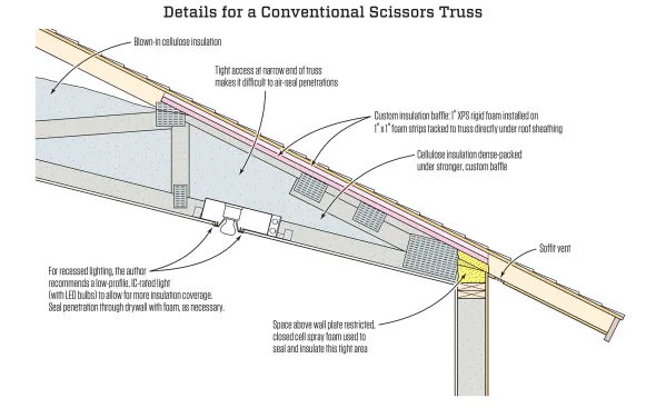
For a slight boost in R-value and to create a vent space that won’t be crushed by the pressure of dense-blown cellulose, the author’s company installs a custom insulation baffle in cathedral-roof rafter bays and scissors-truss bays.
Scissors Truss Pros And Cons
As a sort of hybrid between a rafter-framed cathedral ceiling and a standard flat attic, scissors trusses have obvious advantages for the builder. You get the benefit of the vaulted ceiling and the extra headroom, without the headaches of the rafter detail. Truss framing is quicker and simpler than rafter framing, and it offers better energy efficiency too: You don’t have to run vent channel up the whole length of each bay, you can pile deep blown insulation above the ceiling, and you don’t have a thermal bridge from the ceiling to the roof as you would in a full rafter-framed cathedral.
But scissors trusses have drawbacks in terms of home performance. The main challenge is providing an effective insulation and attic-venting detail at the edge of the roof, where the low profile of the truss above the wall plate restricts the available space. In addition, the tight access at the narrow end of the truss makes it hard to air-seal any penetrations through the ceiling near the outside wall.
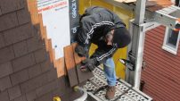
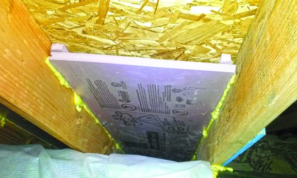
To address venting and insulation, our company has devised a custom ventilation baffle for the roof edge, which we make on site out of one-inch rigid XPS insulation, instead of using a standard foam or cardboard vent channel. We cut one-inch strips from the foam board and tack them to the truss directly under the roof sheathing. Then we fit a piece of foam across the rafter bay to create a one-inch air space under the sheathing, and we fit a piece of foam up under that channel at the outside edge of the wall plate, sealing the foam board to the framing with gun foam. Sometimes, we seal and insulate the whole area above the wall plate with spray foam.
Here, the custom baffle is shown installed in a custom stick-framed roof.
The R-5 foam adds a little insulation value right at the wall-to-roof juncture, where the insulation is thin. But more importantly, the foam board is stiff enough that it won’t collapse from the pressure of the blown insulation when we dense-pack the slope. We’ve been called to existing homes many times for ice-dam issues and found either crushed vent channel or the opposite case: insulation that was installed loosely to avoid crushing the channel and ended up being blown away from the ceiling by wind pressure. Our tougher, custom baffle lets us dense-pack that space without choking off the vent, and it protects the cellulose insulation from wind pressure.
Thin strips of foam hold the R-5 baffle down from the sheathing.
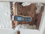
But scissors trusses pose another problem for insulation and air-sealing contractors: They don’t give you much room to work in the attic, especially near the eaves. Builders often like to place recessed lights in sloped ceilings near the edges of rooms, but for the insulation contractor, those light fixtures are a hassle.
It’s our job to air-seal those can light fixtures where they poke up into the attic. Usually, we bring some crawl boards up to the attic with us and screw them down across the sloping bottom chords of the scissors trusses, so that we can lie on something as we try to reach way out into the very end of the slope. In that situation, it’s basically foam and go. We’re working blind—it’s never going to be the perfect air seal that would be possible if you had room to access the area.
And when the tops of the recessed light fixtures extend up near the roof sheathing, they contribute to roof melting in winter, and they complicate the venting problem. Sometimes, we just decide to seal off the one or two bays that have can lights in them, and don’t vent that little section of soffit at all.
Tim Healey
Conventional scissors trusses are hard to detail for high performance at the edge of the roof near the outside wall, because there’s only a small space for insulation, and any ceiling penetrations are close to the roof sheathing in a difficult area for workers to access. The author’s crews use a custom baffle made of one-inch rigid foam to help contain dense-packed insulation.
But that’s a compromise. In fact, to be honest, if you start with a conventional scissors truss, the whole area at the very edge of the roof is always a compromise. No matter what you do, there’s only so much R-value that you can pack into 3 or 4 inches above the wall plate, even if you didn’t have a vent space to contend with. That’s why when we considered scissors trusses for two high-performance projects, we went back to the drawing board.
High-Performance Scissors Trusses
The photos on the following pages come from an advanced custom home project we helped to build a few years ago, but the ideas originally evolved as we worked on the proposal for a similar high-performance Habitat for Humanity project at around the same time. The house was to be a one-story, three-bedroom, two-bath house built on a slab foundation, and the slab was also going to be the finish floor. The challenge we faced was how to keep mechanical systems, including the extensive tubing for a Zehnder energy recovery ventilator (ERV), within the conditioned envelope when we couldn’t put anything in the concrete floor.
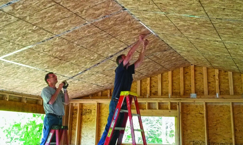
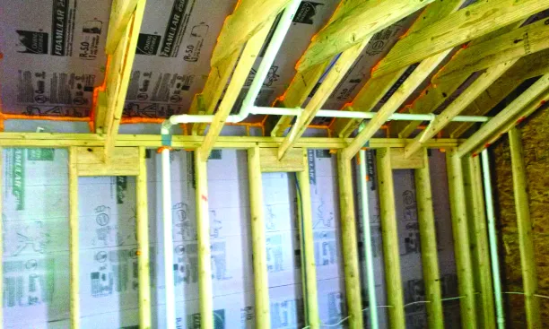
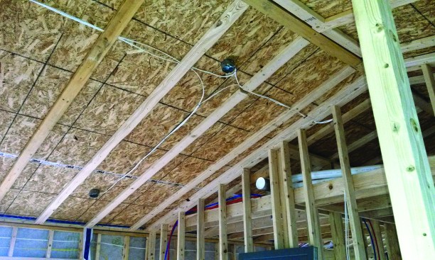
After attaching OSB to the underside of the scissors trusses and sealing the seams with tape, the author’s crew foamed the gaps in the gable end wall to contain blown insulation.
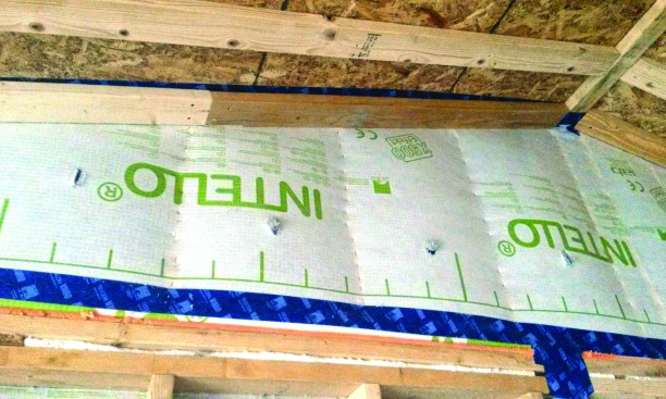
Intello smart vapor retarder fabric was wrapped up the gable wall.
As we sketched ideas on the back of a napkin at lunch, we realized that scissors trusses could help us solve the problem. If we ran the scissors trusses along the whole length of the house, we could construct the air barrier with OSB on the underside of the trusses. We could have vaulted ceilings in the great room and dining area, and fur down the ceilings to build a chase for wiring. Then we could build down a flat dropped ceiling in the kitchen and bedroom areas. The little triangular space between the false ceiling and the air-tight truss-roof underside would create ample room within the conditioned envelope where we could run wiring, ERV tubing, and line sets for the home’s minisplit heating and cooling equipment.
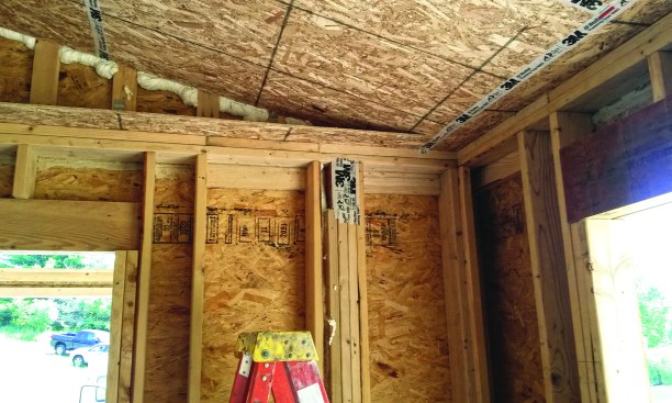
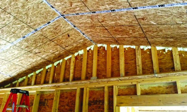
A horizontal strip of OSB at wall-plate height tied the inner wall frame to the outer frame.
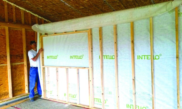
Inner walls were faced with Intello.
To keep the heating load low enough so that one or two minisplit heat pumps could satisfy it, we needed high levels of insulation in both the walls and the ceilings. We chose double stud construction for the walls. Then we designed our trusses with a high heel above the wall plate and with a horizontal shelf projecting inward from the outer loadbearing studwall that could catch the top plate of the inner studwall. This gave us big cavities for plenty of insulation at the wall-to-roof juncture.
Wall Framing Strategy
Whenever you build a double studwall, you have to make some decisions about which wall is load-bearing and about how you’re going to define the air control layer (air barrier) for the building. In this example, the outer wall is the loadbearing wall, but the Intello smart vapor barrier fabric on the outboard face of the inner wall is our primary air barrier. The inner studwall serves as a service cavity for wiring, within the airtight conditioned space.
So to construct this, we ran an OSB shelf on top of the outer wall plates, then set our trusses and skinned their undersides with OSB, taping the seams with 3M 8067 flashing tape. Then we framed the inner walls, applied the Intello to their outboard faces, and set them in place. We folded the Intello under the bottom plates of the inner walls, and set the walls in a bead of adhesive caulk, to integrate the wall air barrier into the slab (which serves as our floor air barrier). We taped the Intello at the top of the inner wall to the OSB on the underside of the roof trusses, to integrate the walls into the ceiling air barrier. Then we furred down the cathedral ceilings and built the dropped ceilings that would serve as our mechanicals chase for the bulky ERV tubing. That way, any wiring, ducts, tubing, or plumbing pipes that ran within the inboard wall or ceiling cavities would be entirely within the airtight conditioned envelope.
Tim Healey
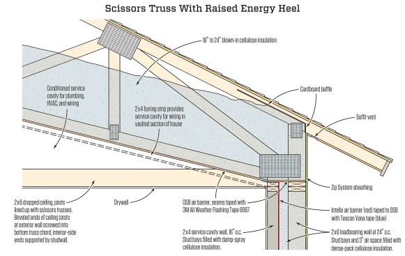
For a practical, high-performance solution, the author’s company devised a raised-heel scissors truss that’s detailed to work well with a double studwall configuration. They sheathed the underside of the truss with an OSB air barrier, sealed with 3M 8067 tape. By furring down from this air barrier and building dropped ceilings, they created protected chases for wiring and ductwork.
The gable end detail got a little complicated. At the ends of the house, we continued the OSB shelf from the bearing walls around to the gable end walls at the same height, and framed the inner wall up under the shelf in the same way. But we brought the Intello membrane in under the OSB shelf and continued that air barrier up the inside of the double wall at the upper portion of the gable. So in that one, small, upper gable area, we couldn’t use the inner wall for a service cavity, because it’s outside the air control layer.
A Simplified Problem
The construction sequence for these jobs, obviously, was different than for a typical production home. The outer walls and truss roof had to be framed first. Then the underside of the trusses was skinned with OSB. Next, the inner walls were framed from inside. Then the ceilings were furred down. Then, interior partitions were framed, and finally the dropped ceilings were framed in.

Furred-down chases and dropped ceilings created space for mechanical and electrical systems within the conditioned envelope.
All this may seem complicated at first glance. But the advantage appeared when it was time to detail the ceiling air barrier and the roof insulation. If this house had been framed with typical conventional truss framing, the complicated interior shapes and different ceiling elevations would have been an energy performance liability. With our method, however, the labor that was expended on the scissors-truss framing, the OSB air barrier under the trusses, the inner wall detail, the furring, and the dropped ceiling allowed us to avoid labor at the air-sealing and insulation stage of the job—and it was a big reason for the home’s outstanding energy performance.
Ceiling lighting fixtures and air supply registers could be kept within conditioned space.
The best illustration of this point is in photo above. At the lower right of that picture, the register for a Zehnder ERV supply duct is roughed in to a 2×6 wall. In a conventional house framed with standard trusses, the back of that wall would be exposed to the cold vented attic, and the wall itself would be a truss with 2x4s on the flat. We would have to figure out how to insulate and air-seal that wall—and in a typical house built by a typical production builder, that whole wall would show up as a cold spot in thermal scans. By the same token, the penetration for the supply register would be a leak point that needed attention (whereas in this house, it’s all inside the conditioned space and it can safely be ignored).
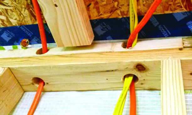
Wiring penetrations in the service cavities did not communicate with the outdoors.
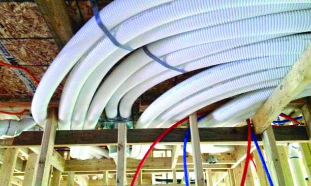
The dropped ceiling accommodated ERV ducts.
Or take a look at the junction boxes in the ceiling. Those locations received low-profile LED disk lights from Commercial Electric, which look like can lights, but can be mounted to a standard depth junction box—and provide 600 lumens while drawing only 11 watts. In typical production homes, those would be can lights that penetrate the air barrier.
And those are just two examples. By taking this approach, we eliminated dozens of similar home-performance headaches. Result: Our blower-door test came in at less than 0.6 ACH50. And although we installed two Mitsubishi minisplit heat pumps in the house for comfort—one 9,000-Btu unit to serve the bedroom, and one 12,000-Btu unit for the rest of the house—the 12,000-Btu unit by itself would be sufficient to heat the entire building.