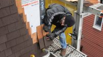
Wall bracing is one of the critical elements of a wood-framed structure, providing resistance to forces that act along the wall plane. In storm-prone coastal areas especially, braced walls help the whole house resist lateral wind forces.
The higher those lateral wind loads are, the stronger the structure must be. That’s why in the zones closest to the coast, where design wind speeds exceed 100 or 110 mph, building codes require new homes to have an engineered design. The design process involves calculating the anticipated wind loads based on the given building’s location, exposure, and dimensions, and then specifying appropriate assemblies to resist those loads. For wood-framed houses, the resulting design ordinarily includes shear walls built using closely nailed structural panel sheathing and rugged hold-downs.
But for typical buildings where expected winds loads are more modest, builders can use prescriptive wall-bracing rules contained within the International Residential Code. The IRC’s Section R602.10 calls for “braced wall lines” composed of “braced wall panels.” The location, width, and construction details of these braced wall panels, as well as the materials that can be used to build them, are spelled out in the code’s text, tables, and illustrations. Understanding the rules in Section R602.10 is critical for builders seeking to streamline their profit margins by optimizing the framing package, but it will also help those building in higher wind zones understand what’s involved in an engineer’s design.
Section R602.10 of the International Residential Code allows wide flexibility in how builders can brace against wind loads, but it’s not a simple prescription. Here’s a clear path through the maze of options.
Defining Braced Walls
In practice, braced wall panels as understood by engineers and code officials are nothing more than areas of framed wall containing no door or window openings and which have let-in bracing, diagonal board sheathing, or some sort of code-approved sheet material to stiffen the structure against racking. In many cases, the only difference between a shear wall and braced wall is the inclusion of hold-down brackets on the shear wall.
Keep in mind that not all sheathed walls constitute a code-defined “braced wall panels.” To count toward the total bracing requirement, a sheathed segment has to be tall enough to cover the full wall height and wide enough to satisfy minimum strength requirements. Sheathing above and below windows does not count. Neither does sheathing on sections that are too skinny, such as thin strips of wall between windows or at corners — tall, narrow pieces of wall can’t be depended on to provide the needed bracing.
Eight options. The code explicitly allows eight different wall-bracing methods, each involving a different material (see “IRC Wall-Bracing Methods”). But that flexibility of multiple bracing options also adds complexity to the prescriptive measures allowed. Here, we’re focusing primarily on what the code calls “Method 3”: bracing with wood structural panels, such as plywood or OSB. The total wall area you must devote to bracing is less if you use plywood and OSB than if you rely on other materials. But this is not to imply that Method 3 is any better or stronger than any of the other methods allowed; every method described in the code will work. However, structural wood sheathing offers builders wider flexibility in the building design, particularly when it comes to the placement of window and door openings (see “Comparing Wall-Bracing Options “).
| IRC Wall-Bracing Methods |
|---|
Method 1: 1×4 let-in wood bracing or equivalent metal bracing Method 2: Diagonal board sheathing Method 3: Wood structural panel sheathing Method 4: 1/2-inch structural fiberboard sheathing Method 5: 1/2-inch gypsum board Method 6: Particleboard sheathing panels Method 7: Portland cement plaster Method 8: Hardboard panel siding |
Any of the materials listed above can be used to make braced wall panels as defined within the IRC. For Method 1 (let-in bracing), braces must be applied at a 45° to 60° angle. For all other methods except Method 5 (gypsum board) and the “fully sheathed” version of Method 3 (wood structural panels), braced wall panels must be a minimum of 4 feet long (measured horizontally along the wall line). Gypsum board braced wall panels must be a minimum of 8 feet long (or 4 feet long, if gypsum board is applied to both sides). But if buildings are fully sheathed with wood structural panels, braced wall panels may be narrower than 4 feet in many situations. For all braced wall panels, materials must be fastened to framing as specified in the code. |
Comparing Wall-Bracing Options
Engineered Shear Walls
Engineered shear walls are used when wind loads equal or exceed 100 mph (2006 IRC) or 110 mph (2003 IRC). An engineer must calculate project-specific wind loads and specify the size, location, and construction of any shear walls accordingly. Shear walls ordinarily have tight nailing at edges and engineered hold-downs at each segment. Shear walls can be spaced in multiple segments as narrow as 271/2 inches for wind design.
IRC “Method 3”
The IRC’s “Method 3” can be used for relatively low wind loads below 100 or 110 mph. Plywood or OSB fastened to some areas of each wall stabilizes the walls against racking from the force of the wind. “Braced wall panels” (areas of clear wall covered with plywood or OSB) must be at least 4 feet wide, extend to the full wall height, and be located at or near each end of the wall (but no more than 25 feet apart).
IRC “Fully Sheathed”
If a building is fully sheathed with plywood or OSB, the IRC allows a reduction in the total area devoted to braced wall panels. Also, sheathed areas narrower than 4 feet may be counted as braced wall panels (minimum width depends on the height of the wall and the height of adjacent openings). However, all corners must be constructed as braced wall panels.
Limitations of prescriptive measures. Before you start applying IRC Section R602.10’s rules to your building, be sure you don’t need an engineer. Several factors may push a project outside the IRC’s scope:
• Wind-speed zone. To qualify within the 2000 or 2003 IRC, the house must be in a design wind-speed zone below 110 mph. In the recently published 2006 IRC, that threshold has been lowered to 100 mph.
• Story height. Story height cannot be more than 11 feet 4 inches (10 feet of stud height plus 16 inches for floor framing). There is an exception in Section 3 of the IRC that allows studs as high as 12 feet and still falls within the IRC’s scope. In that case, the builder has to increase the braced-wall amount by 20%.
• Number of stories. The IRC is limited to buildings with three stories or fewer.
If a project falls outside the IRC’s scope, whether because the building is too tall, the walls are too high, or the wind exposures are too extreme, then an engineered design is required.
Complying with “Method 3”
Although the details get complicated, following IRC Section R602.10’s rules is simple in concept: You just have to provide full-height braced wall panels of the required width, at the required locations, accounting for at least the required minimum percentage of the total wall length.
The dimensions and proportions of bracing panels may vary depending on factors such as the wall’s height, the size of any openings in the wall, and the number of stories above the wall. But in all cases, the braced wall panels need to line up within a “braced wall line” (Figure 1). Offsets are allowed within limits: Individual offsets may be as much as 4 feet, and the total offset from outside to outside may be as much as 8 feet.
Figure 1. Braced wall lines may include offsets. However, the maximum offset is 4 feet, and the total offset from one side to the other may not exceed 8 feet.
All exterior walls have to be braced, and the distance between braced wall lines cannot exceed 25 feet. Again, there is an exception: Braced wall lines as far as 50 feet apart are allowed if the total amount of braced wall panel area is increased to compensate for the greater distance between the braced wall lines. While not immediately apparent, this exception makes sense: If the house is wider, it catches more wind and experiences a greater total load. Think of a sail: The bigger the sail, the greater the force. In a wide house, that translates to more work that the braced walls have to do. For buildings up to 50 feet wide, you have a choice: (1) Include an interior wall equipped with bracing, or (2) increase the area of braced panels in the exterior walls. One way or the other, the increased load has to be handled. If you choose to beef up the exterior walls, the code provides a proportional formula for increasing the total width of braced wall panels to beef them up. When houses get wider than 50 feet, however, you have just one choice: Include an interior braced wall line, no matter what.
“Fully Sheathed” Structures
Besides the basic Method 3, there’s another choice using OSB or plywood: Fully sheathe the structure as described in paragraph R602.10.5 of the IRC. For the buildings to qualify, all exterior walls must be sheathed in plywood or OSB, including areas above and below windows or doors, and there have to be sheathed panels (not windows) at all corners.
When you fully sheathe the building, you can reduce the total braced-wall amount by applying a multiplier of either 0.8 or 0.9, depending on the height of openings in the wall. If the wall has door openings (measuring up to 85% of the wall height), the total bracing amount can be reduced by only 10%. If walls contain just window openings (up to 67% of wall height), the total bracing amount can be reduced by 20%.
But just as important, the fully sheathed method lets you count full-height wall segments narrower than 4 feet as braced wall panels, in many cases (see “Length Requirements for Braced Wall Panels”). For example, for an 8-foot-high wall with typical-sized windows, even a 24-inch-wide section counts toward the wall-bracing total. This gives the builder greater leeway in placing window and door openings in the wall, while still achieving the code-required bracing.
Note: Braced wall panel “length” requirements for houses that are fully sheathed depend on the height of the wall and the height of adjacent openings (as a percentage of the wall’s height). “Length” here refers to the horizontal wall distance; on site this may be commonly referred to as the braced panel’s “width.”
There are trade-offs, however. For one thing, the fully sheathed method complicates the issue of determining the minimum braced panel width. The basic Method 3 sets a single, simple minimum width for braced wall panels: They all have to be at least 4 feet wide. By contrast, the rules for a fully sheathed building vary depending on the wall height and on the size of adjacent openings.
And there’s another caveat. Under the basic Method 3, braced wall panels can be located as far as 12 feet from the end of the braced wall line — bracing doesn’t necessarily have to be located at corners. But to use the fully sheathed method, the builder must construct all exterior corners as braced wall panels of the required minimum width, including minimum corner panel widths, as shown in the table on page 54. This means that if a builder wants to place windows or doors very close to building corners, he will have to look back at the regular Method 3, and his braced wall panels will have to make up a greater proportion of the total wall.
APA’s “Narrow Wall-Bracing Method”
In modern house designs, even the relatively flexible rules for the fully sheathed house may constrain the placement of windows and doors too much for some builders. One common issue has been the need to flank garage-door openings with braced-wall sections measuring 4 feet or wider. The bracing is important, but the space enclosed by making the whole garage wider by 4 feet or more is not particularly useful, and the wider room spans boost the cost of foundation and framing and may affect the way the house is sited in relation to setbacks.
To address this problem, APA – The Engineered Wood Association, a group representing plywood and OSB manufacturers, has developed and tested alternatives that have now gained code acceptance. Only allowed at garage doors in a fully sheathed house, the “APA Narrow Wall-Bracing Method” (Figure 2) uses wood studs and OSB or plywood sheathing, but with some different framing details. Key elements:
• an overlapping header (headers must run past door openings all the way to the far edge of the braced-wall section);
• extra nails (3 inches o.c. nail spacing);
• beefed-up foundation anchorage (two anchors with plate washer into the concrete per braced-wall section).
The benefit to builders is that if they follow the new specs, they can use braced-wall sections as narrow as 16 inches.
Figure 2. To address the particular problem of braced walls next to garage doors, the newest IRC version now includes this method developed by APA – The Engineered Wood Association. Close nail spacing, an overlapping header that extends to the end of the wall, and anchor bolts help offset the reduced segment width.
APA’s method is based on equivalency testing: APA tested some already-permitted braced-wall sections to evaluate their strength, and then designed new, narrower wall assemblies that could supply the same tested structural capacity. APA’s method was made part of the 2004 Supplement to the IRC, and is also written into the new 2006 IRC. ~
The information in this article is based on staff research and interviews by Ted Cushman with Vladimir Kochkin, research engineer with the NAHB Research Center.