
This article is part of the Radiant Heating Skills Workbook.
The thought of adding a complete central heating system to an existing house conjures up images of hours of “Sawzall surgery” followed by more hours of repairing drywall and finishes. This is especially true for forced-air systems, with all their associated ductwork.
But with the right approach, central hydronic heating can now be added to many homes with minimal disruption to existing finishes.
Advantages of Water
When it comes to retrofit systems, hydronic heating has a basic advantage over forced air. The water used to convey heat is almost 3,500 times more “thermally concentrated” than air. A cubic foot of water absorbs about 62.4 Btu for each degree Fahrenheit its temperature increases. By comparison, a cubic foot of air only absorbs about 0.018 Btu for the same temperature rise. Divide the first number by the second and you’ll get a ratio of almost 3,500.
In practical terms, this means the amount of water that has to be moved to carry a given amount of heat is much smaller than the volume of air required for the same task. Under typical operating conditions, a 3/4-inch tube can carry the same amount of heat as an 8×14-inch rectangular duct. It’s obviously easier to conceal the tube in a framing cavity.
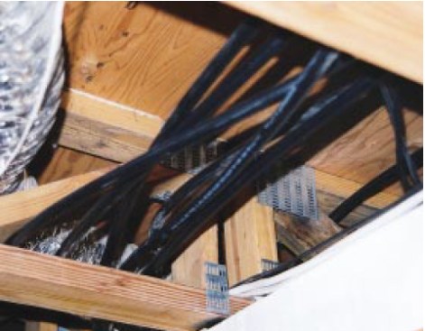
The 1/2-inch PEX-AL-PEX tubing used in this retrofit hydronic system can be snaked through framing cavities much like electrical cable.
Plastic Piping
Small tubing is the key to easy retro- fitting. With copper, however, the difficulty of making intermediate piping connections is still a major concern. You can slide a 10-foot length of copper tubing down a joist cavity, but you still have to saw a hole in the ceiling to solder the joint. That’s where PEX (cross-linked polyethylene) tubing and its newer cousin, PEX-AL-PEX tubing, enter in. Because PEX and PEX-AL-PEX tubing comes in continuous coils and is easily bent by hand, it can be snaked and pulled through concealed framing cavities much like electrical cable.
PEX is well known for its use in radiant floors, where supply temperatures usually don’t exceed 130°F. PEX-AL-PEX, which has an aluminum core with PEX veneers inside and outside, has higher temperature and pressure ratings than pure PEX. PEX-AL-PEX with the ASTM- 1281 designation is rated for continuous operation at 210°F at a corresponding pressure of 115 psi. This makes PEX-ALPEX suitable for use with higher temperature radiant heat, which typically operates at water temperatures between 160°F and 200°F with pressures no higher than 30 psi.
There are a couple of other advantages of PEX-AL-PEX when it comes to retrofit jobs. Because of its aluminum core, the tubing retains its shape when bent. This can help a lot if you’re trying to guide the leading end of a tube through small openings several feet from your reach. Also, if the pipe has to remain exposed, PEX-AL-PEX is easy to straighten for a neat appearance. The tubing used for the house in this article was 1/2-inch AlumiPex, from Weil-McLain ( www.weil-mclain.com).
The House
The building we retrofitted was a small passive solar house built in 1983 in upstate New York. Backup heat was provided by a small woodstove. Although the existing system worked well, the retired owners were interested in adding a fully automatic heating system for times when they were away in winter. The fact that the local utility was installing a gas main up the road made it the time to act.
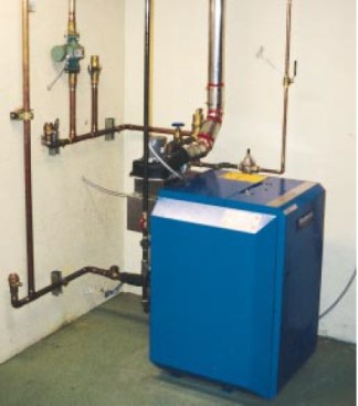
The boiler uses a 3-inch-diameter stainless steel power venting system to avoid the need for a new chimney.
The house had an existing utility room for the water heater and firewood storage. Available space for the boiler was tight but adequate. We selected a power-vented boiler to eliminate the need for a new chimney. Exhaust gases exit through a 3-inchdiameter stainless steel vent pipe to an outside terminal. We chose a boiler with output somewhat larger than the required heating load, in case the owner later wanted to add domestic water heating or a future zone for garage heating.
We took advantage of the fact that the home’s floor deck was framed with openweb floor trusses. It allowed us to snake the 1/2-inch tubing from the open-frame ceiling of the mechanical room to almost any other location in the floor deck. From there it was a matter of how to bring the tubing up to floor level.
In some locations we routed it through stud wall cavities. In other spots masonry walls didn’t allow us this option. Here the tubing was surface-mounted using Genova CPVC stand-off clips to hold it in place. We installed the clips approximately 24 inches apart along straight lines. Once the clip is mounted the tubing simply snaps into the open end.
Panel Radiators
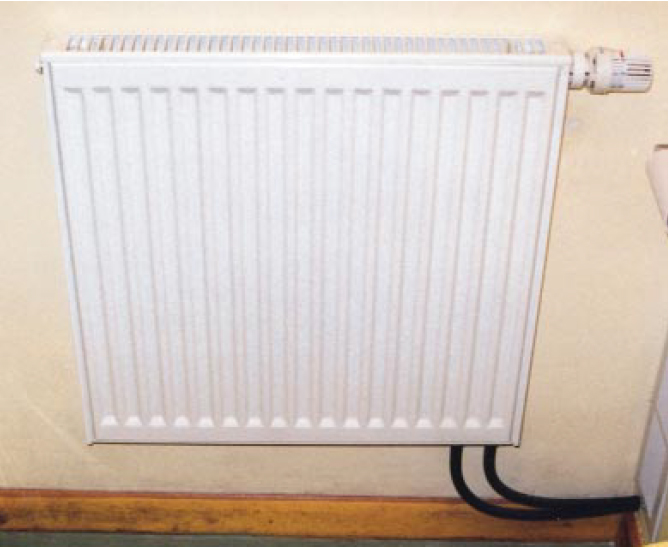
We selected European-style panel radiators from Buderus (Bosch Thermotechnology; www.bosch-climate.us) as the heat emitters. They allow sufficient heat output using much less horizontal wall space than fin-tube baseboard. This was especially important in the compact bathrooms and kitchen where available wall space was sometimes less than 3 feet. In comparison to baseboard, panel radiators also deliver a higher percentage of their heat output as radiant rather than convective heat. This improves comfort, especially in rooms with tall ceilings where convection tends to increase air temperature stratification.
We used 24-inch-high panels that varied in width from 24 to 48 inches. Each unit was only 21/2 inches wide. The panel radiators have supply and return connections on the bottom that allow several tubing options. Weil-McLain supplies tubing connectors that match the Euro-conical threads (close to an NPT thread, but with a slightly different angle) on the Buderus radiators. We mounted the radiators approximately 6 inches above the floor, using simple spring-loaded wall brackets.
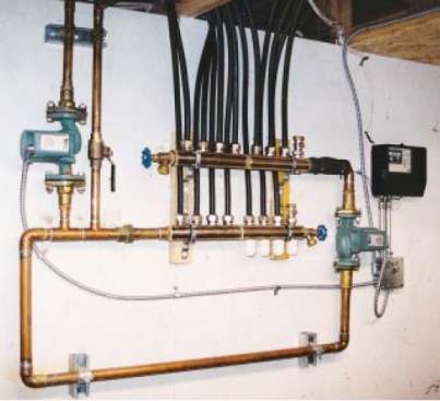
The manifold loop is installed in a mechanical room where it is easily accessed. The injection pump is at left, above the closely spaced tees. Halfinch PEX-AL-PEX circuits begin and end at the manifolds. The supply manifold is on top. The system control and manifold circulator are at far right.
Room-by-Room Control
Each panel radiator was equipped with a non-electric thermostatic valve operator. It’s the small white plastic knob seen at the upper right corner of the radiator in the photo on the previous page. The knob is set for the desired comfort level in the room. It operates the radiator’s valve as needed to prevent overshooting this setting. Unlike conventional zone controls that are either on or off, thermostatic radiator valves can make small flow adjustments to maintain stable room temperature.
The thermostatic valves make it possible for each room to adjust to changing room loads. For example, on sunny but cold days, the valves on radiators in south-facing rooms with passive solar gains quickly close to prevent further heat input, while those in north-facing rooms continue to allow the necessary heat input.
To allow each radiator to operate independently, we used a “home-run” piping system from a manifold set mounted in the mechanical room (see photo above). With one exception, each radiator has its own supply and return tube from the manifold station. The manifold set is the same as that used for hydronic radiant floor heating; it just operates at a higher water temperature in this system.
System Controls
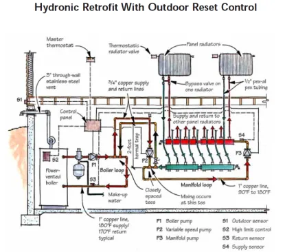
The illustration above shows a piping schematic of the overall system. The temperature of the water supplied to the radiator circuits changes based on outdoor temperature. The colder it is outside, the warmer the water supplied to the radiators.
This strategy is called outdoor reset control. It has been used with radiant floor heating systems for years, but is equally applicable to other types of hydronic heating. The idea is to make heat output from the radiators equal to heat loss from the house over a wide range of outside temperatures — sort of like a cruise control for the heating system. It has the advantage of minimizing variations in room temperature as compared with radiators that must cycle on and off because they’re always supplied with high-temperature water.
Conventional electric thermostats can also be used in lieu of thermostatic radiator valves for zone control. With this setup, each thermostat operates a lowvoltage valve actuator on the return manifold. When signaled by the thermostat, the actuator opens a valve, which allows flow through a single tubing circuit. An “end switch” in the actuator then signals for boiler and circulator operation.
Regardless of which type thermostat is used, water temperature is adjusted by mixing hot water from the boiler with return water from the radiators. The manifold loop shown in the schematic has water circulating through it whenever any radiator needs heat. The rate of hot-water injection into the loop depends upon the speed of a variablespeed circulator (P2 in the schematic) that is regulated by a micr-oprocessorbased controller. The faster this circulator runs, the warmer the manifold loop gets, and the greater the heat output of the radiators.
Sizing Considerations
Panel radiator manufacturers publish sizing tables showing heat output over a wide range of sizes and water temperatures. The first step is to obtain a roomby- room heat load estimate. Next, select a “design” water temperature, (the water temperature supplied to the panels under maximum heating load). 180°F is common, although lower temperatures are certainly possible. The trade-off is that lower water temperatures require larger panels to yield the same heat output.
Since a home-run piping system supplies the same temperature to each panel, individual panel sizes can be easily picked from the sizing table based on the same water temperature. In some cases, several different panel sizes and shapes may be capable of providing the necessary heat output. Select one that best fits the available wall space. Be sure to allow 4 to 6 inches under the panel (for air to flow under and then up the back of the panel). Also allow for the protrusion of the thermostatic knobs if you use them.
When radiators are equipped with thermostatic valves, oversizing is not a problem. In fact, I like to slightly oversize bathroom radiators to allow for a fast temperature boost when desired — for example, before taking a shower.
As a conservative rule of thumb, 1/2- inch tubing is adequate for delivering up to 20,000 Btu/hr per circuit. Since individual panel radiators seldom put out this amount of heat, 1/2-inch tubing is capable of handling multiple panels. For individual panel control when supplying several panels on one circuit, each radiator should be equipped with a bypass valve. This allows two or more radiators to be piped into a series circuit, but still to be controlled as individual units. When a given panel is “off,” the flow bypasses it without giving up heat.
Flexible Solution
The home-run piping and panel radiator technique used for this home could easily be used to “extend” an existing hydronic system into a new addition, or even to supply an entire new home. We’ve done several homes with hydronic floor heating in slab-on-grade first floors, combined with home-run panel radiators or baseboards on the second floor. Sometimes the choice is based on budget, other times it’s based on the desired floor covering.
The general concept of a “home-run” distribution system offers tremendous potential for hydronic systems, both new and retrofit. Systems designed to the exact requirements of the building can be installed with minimal intrusiveness. Given the new methods and materials available, the versatility of hydronic heating has never been greater.
Be sure to check out the rest of the Radiant Heating Skills Workbook.


