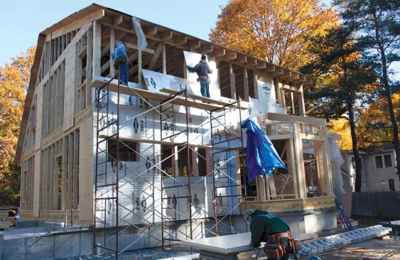
Advance framing and exterior foam are the ingredients for this h…
Editor’s note: This is the first part of a two-part article. Part I will describe framing and exterior sheathing; Part II will cover window and siding installation, air sealing and insulation, mechanical systems, and finishes.
In a previous article, I described an exterior insulation upgrade that our energy-oriented company performed on an older home (see “Retrofitting Exterior Insulation,” 11/09). Early in the fall of ’09, we started work on a new home using many of the same concepts that had allowed us to dramatically improve the older home’s energy performance.
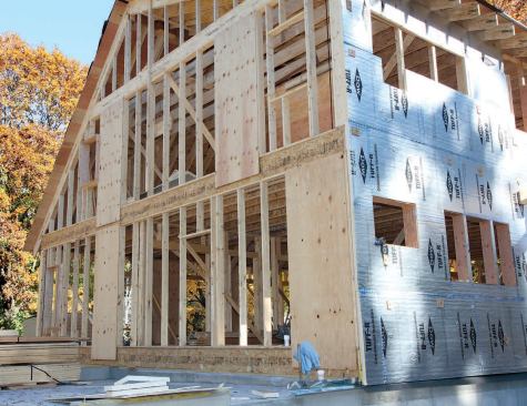
Architect Betsy Pettit of Building Science Corp., who’d consulted on the retrofit job, designed this new building from the ground up. Among her performance-boosting strategies was the use of “advanced framing” — which eliminates redundant and structurally unnecessary lumber — and an exterior skin of insulating foam. Although not an essential ingredient of advanced framing, foam sheathing is a natural fit. On this job, we installed a double layer of 2-inch foil-faced Tuff-R polyiso board directly over the studs. The foam serves triple duty as a thermal break, a drainage plane for any water that gets past the siding, and an air barrier, with no need for supplemental housewrap. All seams and any tears in the foil facing are taped to provide an airtight, waterproof surface. To provide lateral strength to the frame, we installed vertical 1/2-inch plywood shear panels at specified intervals, covering the plywood with 1 1/2-inch foam to match the thickness of the first foam layer.
Advanced Framing In the Field
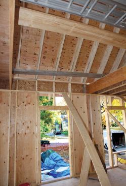
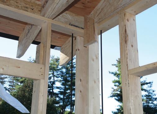
The NAHB developed the advanced framing concept — originally known as “optimal value engineered,” or OVE, framing — back in the ’70s, with the intention of making more efficient use of building materials. In a nutshell, all framing is strictly aligned from the first-floor deck up to the rafters on 24-inch centers. Walls have single top plates, corners are built with two studs instead of three or more, and structural headers are reduced to single members or insulated cores; in non-load-bearing walls, headers are eliminated.
Tying top plates together. Single-member top plates serve only to position and secure the studs, not to support or redistribute offset point loads. When butting plates together, it isn’t necessary to land the joint on a stud. Instead, we use a Simpson TP49 metal splice plate or a piece of wood blocking. Blocking is cheaper and faster to install; where it just won’t fit, as in corners, we use the metal plates. To prevent joint stress and separation, we install the metal plates after standing the walls. Before nailing them off, we throw a strap around a few studs on either side of the joint and pull it tight.
Because a single plate is more flexible than double top plates, it takes a little more time and a few more braces to straighten walls. When we brace the walls, we pull them slightly inward, about 1/4 inch from plumb. Throughout construction, the top plates tend to get forced outward, mostly by rafter thrust before the collar ties are installed. Later, it’s a lot easier to push a wall outward to plumb it than it is to haul it back in, so I like to start with that advantage.
Wall layout modifications. When laying out the front walls, we had to keep in mind how to support the second floor and roof. Although the general framing was consistently aligned from bottom to top, five rough openings didn’t coincide with the 24-inch on-center layout. The situation was further complicated by two doghouse dormers, each with doubled rafters on both sides, that landed off-layout. To transfer these loads, we had to add studs on both floors and squash blocks at the rim joists. Generally, we found that the simplest approach was to lay out the wall according to the plan and install the supplemental framing as needed later.
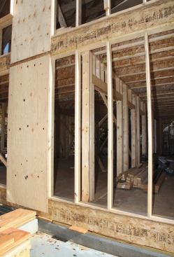
When framing the gables, we adjusted the layout to accommodate the foam sheathing. The first layer of 4-by-8-foot foam sheathing is installed with its edges aligned on stud centers, but because it’s also overlapped at the building corners, it falls off standard layout by its 2-inch thickness. To compensate, we centered the first stud in from the corner at 22 inches and established the 24-inch layout from that point. We used simple two-stud “L” configurations at corners, which allows for slightly better insulation.
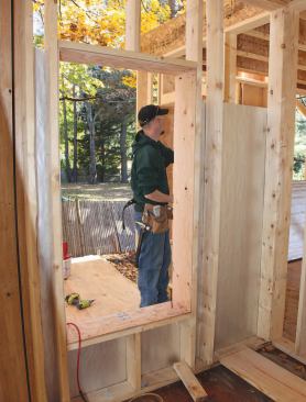
Rough openings on nonbearing walls don’t typically require structural headers or jack studs, so there we installed king studs only, with single 2×6 head and sill members installed on the flat. If sheathing the frame with plywood, you’d cut the headers and sills to the exact rough opening width. But in this case, we lined the openings with 1/2-inch plywood bucks that projected out 4 inches to cap the edges of the foam sheathing. To accommodate the bucks, we added an inch to the height and width of each rough opening.
Partition backers. Instead of standard partition backers, we used single studs at wall intersections and installed ladder blocking to attach them. Again, this eliminates an interruption in the insulation layer typically created in conventional framing.
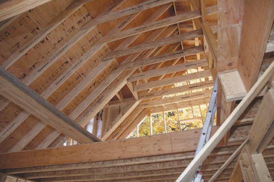
Floor and roof framing. There was nothing unusual about the floors or the roof. We used wood I-joists aligned with the 24-inch on-center wall layout. At the gable ends, we substituted OSB rim-joist material for the I-joists and installed vertical 2×4 squash blocks directly below the studs. We took the blocks from the scrap pile and saved the cost of a few I-joists. On top of the plates, we nailed 2×4 cleats on the flat. Stopped by the squash blocks, this provided a 1 1/2-inch attachment surface for the ceiling drywall while still leaving the end bays accessible for insulation — in this case, closed-cell spray foam at all rims.
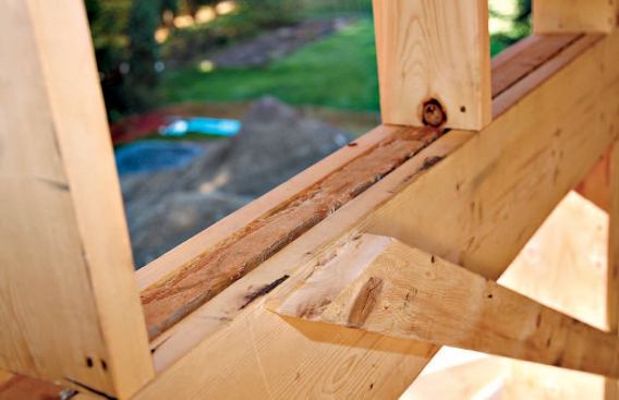
Standard dimensional lumber in the 24-foot lengths we needed for the rafters has to come from old-growth trees, which we prefer not to use. And for the 4-pitch roof in the rear, solid lumber joists on 24-inch centers wouldn’t have had the capacity we needed to handle the area’s snow load plus the weight of the solar panels we’d be installing. So we used 2×12 laminated strand lumber, or LSL, which cuts just like solid dimensional lumber and doesn’t require additional reinforcement at the plates. It’s much harder than solid lumber, though — our standard pneumatic nails bent when we were nailing off the collar ties. We switched to the heaviest-gauge nail the guns would handle and still had to hammer the last 3/4 inch home.
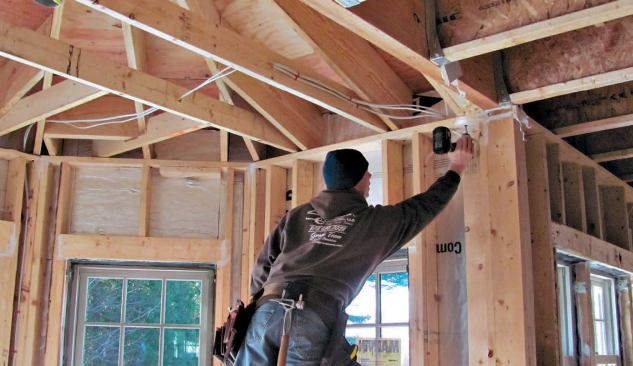
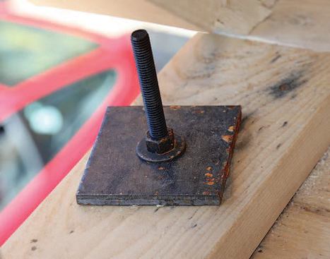
We saved a little time by eliminating conventional metal rafter ties. Instead, we drove 6-inch-long TimberLok (800/518- 3569, fastenmaster.com) screws up through the top plate into the rafters. Where they can’t be driven directly up through the plate underside, they can be sent into the rafter from the front corner of the plate at a 22-degree angle. According to a technical bulletin on the company’s Web site, these screws are code-approved replacements for straps or ties, which is nice because they’re also faster and less obtrusive.


