LED lighting has come a long way in the past 10 to 15 years. It is now found in commercial spaces, high-powered stadium lighting, automobiles, and, of course, homes. Back in 2013, I remember exploring LED tape lighting for a project, but it was extremely expensive, making it impractical.
Now, however, you can find a vast array of LED tape lighting at the big box stores and big online retailers at extremely reasonable prices. Like everything, you get what you pay for, and pricing can vary greatly depending on which product you select.
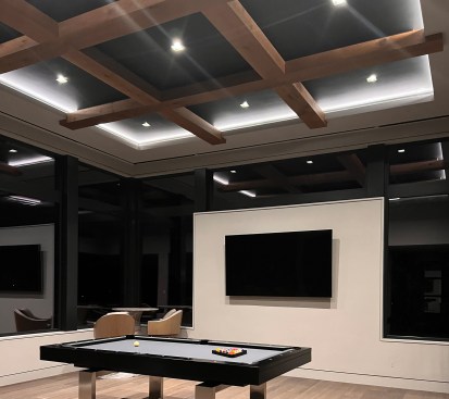
We have found great versatility with LED tape lighting on our projects over the past few years and have been able to explore some fun and creative options with adventurous clients. In this article, I will touch on some of the ways tape lighting can be used to highlight different architectural elements of a home. Called “architectural lighting” in the industry, it is typically installed so the light source is not visible but is hidden by a valance and positioned so the light washes over the intended architectural feature.
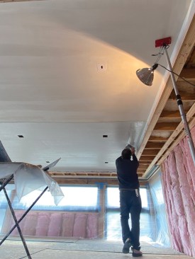
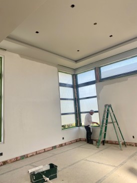
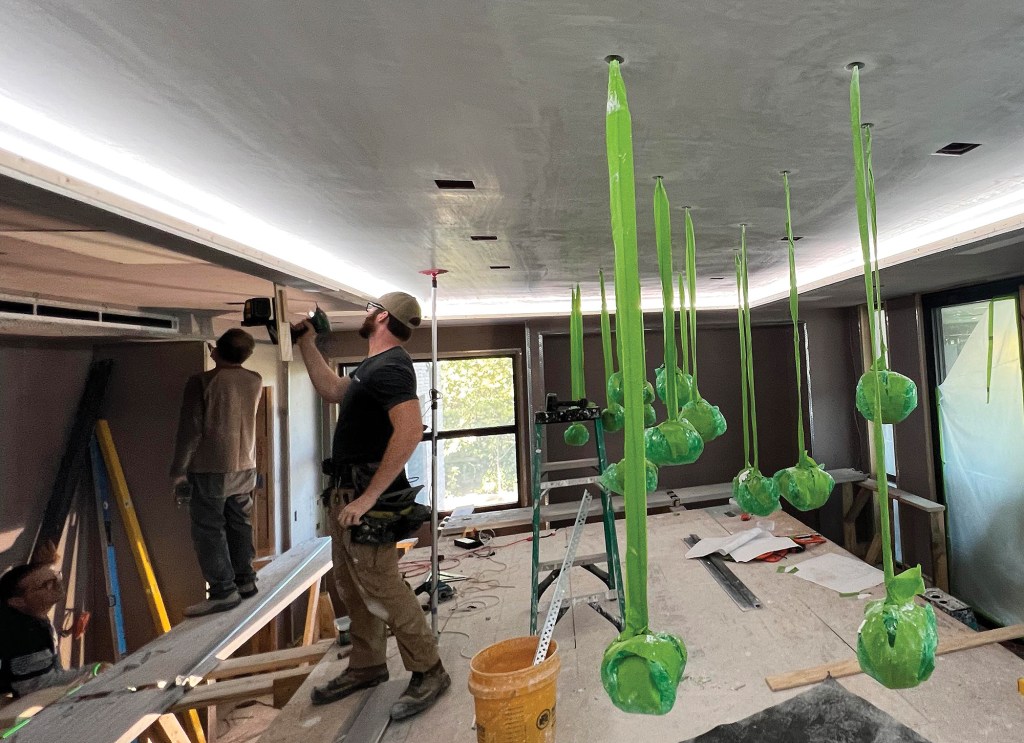
The first step was to plaster the ceiling and down the inside co…
In all the applications we executed, our clients brought us inspiration photos they had collected online. Though they didn’t have any information on how these details were achieved, that wasn’t a problem for us; one of the things we enjoy in the custom-building world is figuring out how to do something we’ve never done before.
First Tray Ceiling
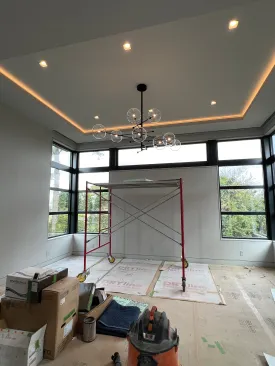
The tray ceiling in one bedroom was the first architectural lighting detail we tackled on this particular project. You can see in illustration below and in the 5th and 6th photos of the slideshow above that the amount of open space from which the light emits at the perimeter of the tray ceiling is very small; figuring out the ideal opening size for the valance proved to be a key detail.
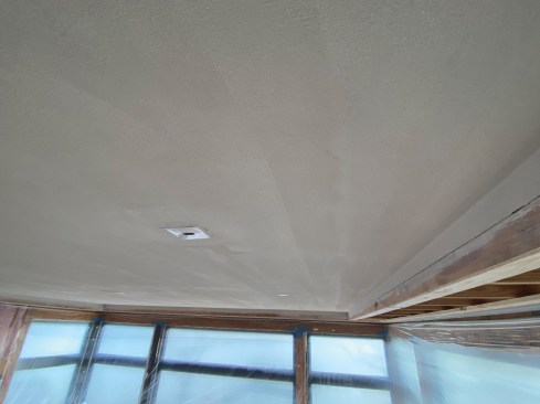
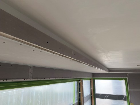
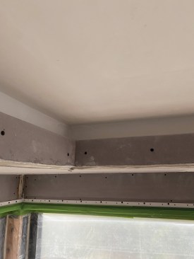
Whenever we have a building detail that we’re unsure of how to execute, we will connect with each trade involved. In this case, that would be the framer/carpenter, electrician, and plaster crew. The framing contractor and I sketched out some ideas on how the detail could be done and quickly realized this was going to be a multi-step process. The plasterer confirmed our concept. We would need to plaster the ceiling and down the wall behind the valance before we completed the framing for the face of the cove element that would support the valance (see illustration, below). To make it simple for the crew hanging the plasterboard, we installed temporary strips of 3/4-inch plywood to define where the plasterboard needed to stop. We then had the plasterers plaster the upper ceiling and sides above the temporary plywood strips.
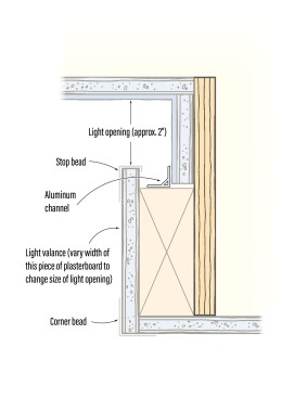
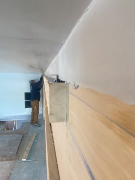
At the perimeter of the ceiling, the author and his crew built a cove to hide recessed LED tape. The 2×4 supports an angled aluminum track that holds the LED tape. On the front face, a ripped piece of plasterboard acts as a valance to hide the LED tape from sight.
Once the plasterwork had been done, we removed the strips and exchanged them for a 2-by ripped to a custom dimension. With this work done, it was time for the electricians to step in and complete the tape light installation.
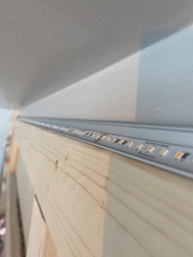
The tape light would be installed on top of the 2-by in an aluminum channel. There are various channel styles, depending on how you want the light to be cast. For this application, we selected an angled channel that would help push the light outward, toward the center of the room. We used construction adhesive to stick the track to the 2-by, allowing a day for it to dry before installing the LED strip in the channel.
During the electrical rough-in, we planned for a low-voltage wire to be installed in one corner of the ceiling to power the tape. Sticking the tape to the track is simple, but there are some connectors to manage where the low-voltage “lead” (power supply) attaches to the lead on the tape. We used an American Lighting product, which comes in 16-foot lengths. Since in most of the rooms, we needed two rolls, we had to plan for a splice. Keeping the distances between lighting elements even so the light wash would be consistent proved challenging. We managed this by drilling a hole through the 2-by and into the wall where we could tuck the small amount of excess wire out of the way.
Once all the LED tape was in place, the electricians energized the transformer with a temporary cord to make sure everything was working properly and the light was cast evenly. The last step was to install the acrylic lens over the track. This lens, which is frosted, obscures the individual diodes and helps spread the light evenly.
On a side note, it’s important to intentionally plan for the placement of transformers with your electrician. The transformers need to remain accessible and be within a maximum distance of the lighting (typically, around 15 feet) to avoid a voltage drop. Good options include the inside of cabinets, closets, and other easy-to-access, out-of-sight locations. For the tray ceiling, we placed the transformers in the attic that backed up next to this space.
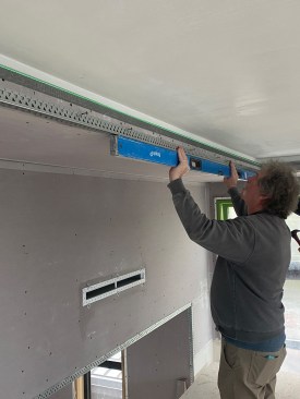
With the lighting installed, we could then install the plasterboard on the lower ceiling area. This “rip” of plasterboard capped the edge of the 2-by, and another rip wrapped up the short face of the tray ceiling. The drywall hangers cut these small pieces, and our carpenters and plaster crew installed them along with the corner beads at the outside corner that defined the perimeter of the tray ceiling and the stop bead (a type of J-bead for plaster) that terminated the edge of the short vertical rise that created the light valance. With crews working side by side, we were able to fine-tune the details of the board, corner bead, and stop bead that capped off the open end of the plasterboard.
To simplify installation of the stop bead, the guys made some gauge blocks at the desired light opening. The blocks allowed them to quickly tack the stop bead in place. From there, we installed the corner bead parallel to the stop bead. As most of you know, nothing is perfect in construction, especially in framing. We found locations where we may have had some dips in the upper and lower ceiling. We had to finesse some areas to find that sweet spot that looked straight in both directions (in and out and up and down) and parallel to the ceiling above. Some of these came down to judgment calls in the field; we had some good eyes looking at it, and we were all able to agree on what looked best. We kept the light on to help us see how any adjustment affected the “cast lines”—the way the light was cast across the ceiling.
Before any new plaster work started, we made sure to protect the light lens with painter’s tape. Once the plaster crew wrapped up, some curing time was needed before paint. During this time, we removed the protective tape from the lens. Our painters preferred to lay down their own tape on the lens to ensure a good cut-in and, since they had to take responsibility for the quality of the work, we obliged.
Once the paint work was underway, we discovered a new challenge with washing wall and ceiling surfaces with light: The drywall/plaster and paint all need to be as close to perfect as possible. The wall wash shows any and all imperfections; as little as a brush stroke out of place can be seen at a close distance.
Initially, the clients asked the author to add concealed LED lig…
The Idea Catches On
Once that first tray ceiling was completed, the client and design team were thrilled with the results and opted to seek out new opportunities to use architectural lighting on the project.
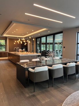
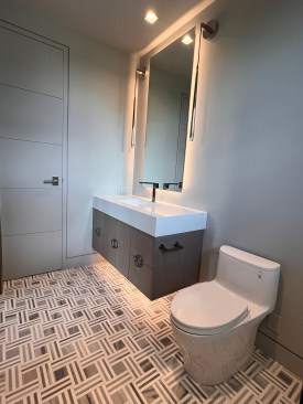
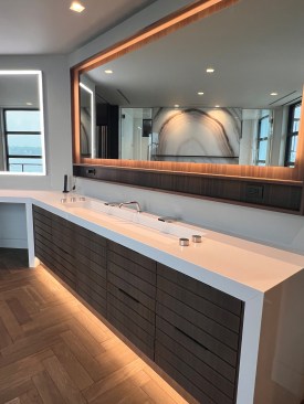
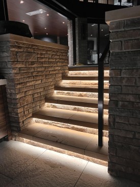
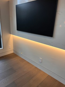
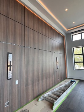
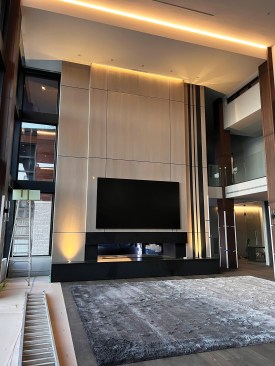
By taking the basic concept of what we learned with the tray ceilings, we were able to extrapolate the details in a variety of ways. Some of the other areas we were able to add lighting to were backlit mirrors, under exterior step treads, and toe kicks. Some other cool and unique areas included a backlit headboard as well as a top- and bottom-lit bump-out for a TV.
In all these applications, one of the most challenging aspects proved to be determining how much “coverage” was needed for the valance that hid the strip light from view. We wanted to allow enough light to escape to wash the walls but not so much that the source of the light could be seen. With the mirrors, we installed the plywood backer that the tape was attached to, turned on the light, and then tinkered with some scrap plywood to find the amount of coverage that looked best. We did this “mock-up” prior to ordering the mirror.
As a builder, we truly love challenges on a job. Finding new elements to include on our projects is fun and rewarding. It helped that we had adventurous clients who trusted us to work through these amazing details.


