After struggling with hip rafters and talking to an old-timer or two, novice framers discover that joining two roofs isn’t that tough — for hips and valleys you just cut all your bevels at 45 degrees, and use 17 instead of 12 for the run on the framing square.
Then it happens: That bid you submitted for the job with the adjoining, unequally pitched roofs gets accepted, and you’ve got to figure out a way to frame it.
One approach is to order twice the framing lumber required and keep cutting hips and valleys until you get it right. Another is to buy a fancy framing calculator and take a course in trigonometry. Or you can use the Zepp method, which requires nothing more than a framing square and a pencil. Don Zepp taught advanced roof framing while I was a student at Williamson Trade School, in Media, Pa., and I feel that his method is the easiest to understand and use in the field.
The key to the Zepp method lies not in fancy math, but in using the framing square to make scale drawings of the crucial angles and cuts, then transferring the measurements from sketch to lumber. The direct correlation between drawings and cuts makes this method accurate and reliable. Master it, and you can handle any of the numerous situations where two roofs of unequal pitches meet, whether at a hip or a valley. For the purposes of this article, I’ll show how to frame the intersection of two hip roofs of unequal pitch.
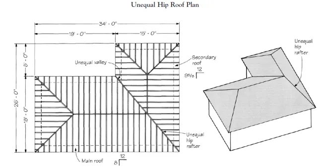
The author begins any complex roof project by making a scale framing plan of the roof (left). This is useful for material takeoffs and as a job-site reference. The perspective sketch (right) shows the location of the unequal hip rafter.
A note before you start: You’ll get the most out of this article if you read it with framing square and a scrap of plywood nearby, so you can perform some of the layout calculations.
Getting Oriented
The first step is to make a scale drawing of the entire roof, locating the exterior walls, ridges, and all rafters, as in Figure 1A. This drawing will serve as a map while you’re putting the pieces together. It will also help you estimate the quantity and lengths of lumber you’ll need. A simple perspective sketch (Figure 1B) helps give an idea of how the finished roof planes will look.
The L-shaped house in Figure 1 has both ridges at the same level. The overhang is 16 inches (measured horizontally), and the fascia runs at a continuous height around the entire house.
Joining these two roofs poses two main challenges: One is getting the two differently pitched planes to meet at the hip (or valley) rafter. The other is to get the fascias to line up.
Establish the pitches. First we should establish the pitch of both roof planes. We’ll start with the knowledge that the main roof has an 8 / 12 pitch. How do we figure the pitch of the secondary roof?
In this article, when I use the word “pitch” I mean the ratio of rise in inches over 12 inches of run. From the plan, we see that the total rise of the secondary roof is the same as that of the main roof — 6 feet. The total run of the secondary roof is 7 feet 6 inches. To convert this to inches of rise per 12 inches of run, use this formula:
12 inches ÷ Total Run x Total Rise = Inches of Rise (Unit Rise)
or
12 inches / 7.5 feet x 6 feet = 9.6, or 9 5/8 inches unit rise
So 9 5/8 / 12 is the secondary roof pitch.
Lining Up the Fascia
Look at Figure 2A, which shows the two differently pitched common rafters. It would seem that lining up the fascias and cornices so you have equal overhangs on both pitches would be impossible, since the rafters of the two roofs extend beyond the plate at different angles. But it’s really not that tough.
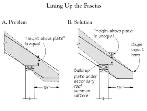
Where roofs of unequal pitch join, it requires careful layout to create equalwidth soffits with equal-height fascias. Drawing A superimposes the common rafters for the two roof pitches, and illustrates the problem that occurs when roof layout starts at the outside edge of the exterior walls. Drawing B shows how the author solves this problem by starting his roof layout at the ends of the rafters and raising the wall plates under the steeper-pitched roof.
Making the fascia meet. To keep the overhang the same and line up the fascia, you must begin the roof layout from the inside top edge of the fascia, not from the outside of the exterior walls. Then you build up the wall plate under the steeper secondary roof, as in Figure 2B. The buildup equals the difference between the unit rise of both roof pitches. In this case, with unit rises of 8 inches and 9 5/8 inches, the difference is 1 5/8, or 1.6 inches. So the plate must be built up 1.6 inches per level foot of overhang.
Since the overhang is 16 inches, or 1.33 feet, the total buildup equals:
1.33 feet x 1.6 inches per foot = 2.13, or 2 1/8 inches
Rather than building the plate up exactly 21/8 inches, I use an extra 2x top plate (11/2 inches thick) and increase the rafter height the remaining 5/8 inch by adding it to the “height above plate” distance that I use to find the birdsmouth level cut.
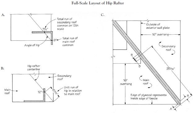
The key to the author’s method lies in making a full-scale drawing of the corner where the unequally pitched roofs meet, then transferring measurements from drawing to lumber. On a sheet of plywood, he first establishes the angle of the hip rafter, using the total runs of the two roofs (A). Next, he derives the unit run of the hip rafter in relation to the main roof (B). Finally, he completes the scale drawing with walls and soffits to establish critical dimensions for cutting the hip (C).
Finding the Pitch of the Hip
Once you’ve temporarily supported the ridges with a few common rafters, you can lay out the hip rafter. I do the layout on a sheet of plywood. Using one corner, I start by drawing the angle of the hip and then develop this line into a fullsized plan view of the roof corner. From this drawing I can pull exact measurements for my bevel cuts.
Hip angle. Using the framing square’s 12th scale, find the hip angle as shown in Figure 3A. Draw a diagonal line between 9 feet (the run of the main roof) on the tongue of the square and 7 feet 6 inches (the secondary roof run) on the blade. This gives the angle of the hip rafter.
Unit run of the hip. In a hip roof with equal pitches, the unit run of a hip or valley rafter is 17 inches for every 12 inches of run in the main roof. For example, in an equal hip roof with an 8 / 12 pitch, the pitch of the hip rafter would be 8 / 17. But here it will be different, since the hip rafter doesn’t lie at 45 degrees to the commons.
The pitch of the unequal hip rafter can be expressed in relation to either the main roof or the secondary roof. Since you need only one set of numbers to lay out the cuts, let’s work with the main roof, which has a unit rise of 8 inches.
Find the hip’s unit run as in Figure 3B. Lay your square in the corner of the plywood drawing, working from the side of the diagonal line that represents the main roof. Keeping the outside edge of the blade flush with the edge of the plywood, slide the square until the 12-inch mark on the tongue intersects with the hip. Make a mark there, then measure the distance from the mark to the drawing’s corner — this is the hip’s unit run. It should measure 15 5/8 inches.
Unit run of hip = 15 5/8 in.
By the way, the unit run for the shallower pitch roof will always be less than 17 inches, while the unit run for the steeper pitch will always be greater than 17 inches.
So now we know the pitch of the hip rafter in relation to the main roof:
Hip pitch = 8 / 15 5/8
Laying Out the Hip
Working on the plywood drawing, next snap lines to define the soffit overhang, fascia, and wall framing at full scale, as shown in Figure 3C. Locate the centerline of the hip rafter not at the corner of the plates, but at the corner of the two intersecting fascia boards. Extend this centerline back to and beyond the wall plate. You’ll notice the hip rafter doesn’t sit on the corner of the two wall plates; it never will. In an unequally pitched hip roof, the hip will always fall on the wall plate supporting the steeper pitched roof. With the full scale drawing completed, it’s time to start putting some marks on a piece of lumber.
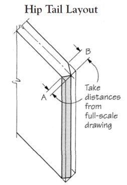
To figure the bevel cuts at the hip rafter tail, take distances “A” and “B” from the full-scale layout drawing in Figure 3.
Hip tail. First lay out the tail end of the rafter, as in Figure 4. Using the unit run and rise of the hip, 8 / 15 5/8, draw a plumb line on both sides of the rafter end with the framing square. You can then take deductions for the sidecut angles directly from the fullscale drawing — distances “A” and “B” in Figure 3C. Since you’re taking these measurements from a plan drawing, make sure you measure perpendicular to the plumb line — not along the rafter edge. Hold off cutting the tail until you lay out the birdsmouth.
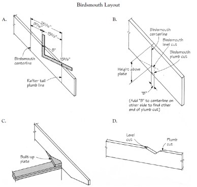
To locate the birdsmouth cut, first measure the horizontal distance from the tail to the plate on the full-scale drawing (Figure 3C). Step off this distance, 251/16 inches, and draw a plumb line (A). The plumb line represents the centerline of the birdsmouth cut. Locate the level cut by measuring down the birdsmouth centerline the “height above plate” distance of the steep roof common rafters (B). To lay out the plumb cut, add and subtract distance “B” perpendicular to the birdsmouth centerline mark, as shown. Because the hip rafter doesn’t cross at the corner of the walls (C), the birdsmouth plumb cut is cut at an angle (D).
Birdsmouth. On the full-scale drawing, measure along the hip rafter centerline from the inside corner of the fascia to the point where the centerline meets the outside of the wall plate. This distance should measure about 25 1/16 inches. Now use the framing square to step off this distance from the plumb line at the tail, just as you would with any rafter. The first step-off accounts for 15 5/8 inches. You’ll have to add the remaining 9 7/16 inches by measuring perpendicular to plumb, as in Figure 5A. Mark a plumb line; this represents the centerline of the birdsmouth cut. Extend this line around the entire rafter.
Heel and seat cuts. Next, lay out the plumb and level cuts for the birdsmouth. Here again, we’ll simply steal the measurements from our full-scale drawing.
To lay out the level cut, measure off the “height above plate” distance (see Figure 2B) along the birdsmouth centerline and draw a perpendicular line to mark the level cut. The “height above plate” for the hip rafter is the same as for the secondary roof common rafters, since the hip falls on the secondary roof plate.
To lay out the plumb cut, take measurement “B” from the full-scale drawing (Figure 3C) and transfer its dimensions to the rafter on both sides of the centerline of the birdsmouth, as shown in Figure 5B. Again, measure perpendicular to the centerline mark for the birdsmouth, rather than along the length of the rafter.
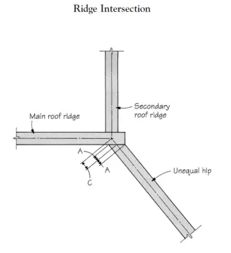
To figure the cheek cut at the top end of the hip rafter, the author makes a fullscale drawing of its intersection with the main roof ridge, then transfers measurements
Cutting to length. Once the birdsmouth is laid out, make a fullscale drawing of the hip-to-ridge connection, as in Figure 6. You’ll use this to steal measurements for finding the length of the hip.
First, we need to step off the distance to the theoretical center point where the hip meets the ridge. Take the run of the main roof (9 feet), and using your square and the pitch of the hip in relationship to the main roof — 8 inches and 15 5/8 inches — step off this distance in the conventional manner. When you’ve stepped off 9 steps, draw a plumb line at that point and extend it completely around the rafter.
This is the theoretical length of the hip rafter. To obtain its true length, deduct distance “C” perpendicular to this plumb line. This gives the true length at the centerline of the rafter. To lay out the cheek cut, you must then add and subtract “A” perpendicular to the true length plumb line.
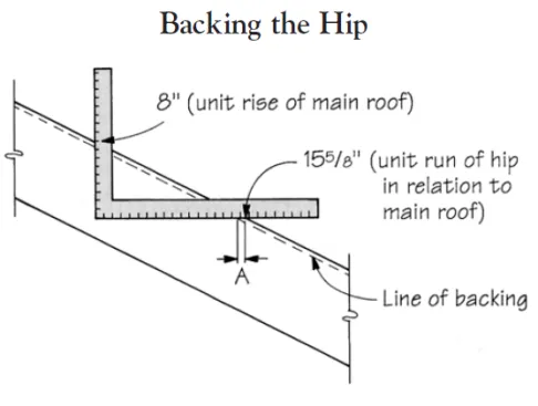
“Backing,” or beveling, the rafter ensures that the roof sheathing will rest flush on the hip. Use the framing square and the hip rafter pitch to determine the line of backing, as shown. Repeat the process on the other side of the hip, using distance “B.”
There you have it! Your unequally pitched hip is laid out and ready to cut. A few details remain.
Backing The Hip
As with any hip rafter, an unequal hip rafter must have its top edge “backed,” or beveled, to match each of the converging roof planes. The question is how much to cut away.
Determine the backing for each roof plane as shown in Figure 7. Place your square on the side of the hip rafter that will face the main roof, using the hip pitch for that roof, 8/155/8. Measure distance “A” along the unit run and mark. This is the line of backing.
Repeat the same procedure on the side of the hip that faces the secondary roof, using the hip pitch for that roof and measuring distance “B”. You’ll have to find the secondary roof hip pitch the same way you found the main roof hip pitch, as in Figure 3B. The hip pitch in relation to the secondary roof measures out at 9 5/8 / 18 13/16. This is exactly the same ratio as the pitch for the other side, but I find it helps to work the two sides separately to avoid confusion, especially when it comes to laying out the jack rafters.
To lay out the jack rafters, the author makes a full-scale drawing of the first two jacks on each side of the hip. From this drawing he finds the angle of the cheek cuts, the run of the first jack, and the common difference used to locate the rest of the jacks.
One important note: Wait until all your layout is complete and you’ve test-fitted the hip rafter before you actually bevel the top edge of the hip. Once the top is beveled, you will have lost an important edge of reference.
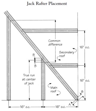
Placement of Jack Rafters
Before you nail up the hip rafter, be sure to lay out the position of the jack rafters. It’s a lot easier on the ground than 20 feet in the air.
To determine the run of the jacks, draw in the first two jacks on the fullscale drawing of the hip rafter, as shown in Figure 8. We can then take all our measurements for the first jacks on each roof directly from the drawing, just as we did for the hip rafter. We can also derive the common differences so we can find the other jacks’ runs.
With your square set on the main roof side of the hip rafter, step off the true run of the first hip jack using the pitch of the main roof hip, 8 / 15 5/8. Mark a plumb line; this is the centerline of the first jack. For each successive jack rafter, step off the common difference. Repeat the process on the other side of the hip, using the pitch of the hip for the secondary roof (9 5/8 / 18 13/16).
Valleys
An unequally pitched valley rafter is laid out in the same way as the unequally pitched hip. The main difference between the two is that valley rafters sit on inside corners, while hip rafters sit on the outside corners.
Each roof will be slightly different. Sometimes, instead of backing the hip, I’ll drop it in relation to the jacks. This still gives plenty of support to the sheathing. Also, I often double the hip rafter for greater strength and more nailing surface. In that case, the backing angle is the same but the line of backing will be lower. But however the details may differ, the Zepp method provides all the fundamentals I need to make sense out of a seemingly impossible situation.


