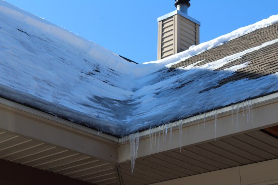
Last December, I was contacted by a couple in their mid-60s who were having repeated ice damming issues on their home. The husband noted that he’d been diligent about raking the roof’s perimeter after snow events over the years, but it was becoming too hard for him to manage. In addition to raking, he said he’d often get up on a ladder and attempt to knock the ice dams off as a last resort—a dangerous task at any age.
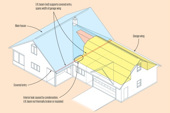
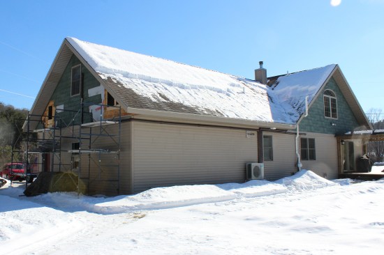
Their modified Cape-style home, built in 2006, was situated on a fairly exposed lot in central Vermont. The homeowners said the ice damming seemed worse on the roof sections above the home’s garage wing. (The garage wing’s roof planed into the main house, forming an L-shaped roof with two valleys). Ice would form along both eaves of the wing, in the bottom of the valleys, and along portions of the north-facing cantilevered eaves of the main house, which served as a covered entry.
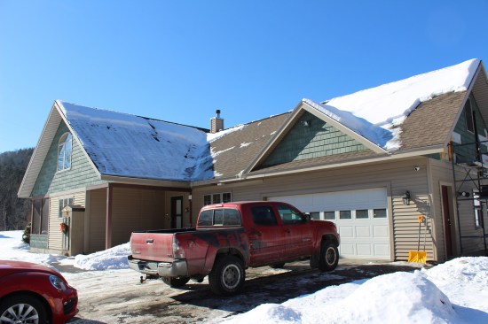
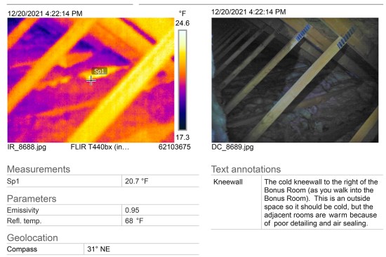
The main house of the L-shaped Cape is in the background, and the garage with the bonus room is on the right.
Ice damming was worst on the garage wing and in valleys abutting the main roof.
Some like it hot. We started with the garage. I inspected the “unheated” space and found it relatively warm (the outside temperature was in the mid-30s). In a corner of the room was a Modine gas heater, which the homeowners said was used intermittently. The garage wing was 26 feet wide by 34 feet long. The unheated garage comprised roughly two-thirds of the wing, while the remaining third was conditioned space. The homeowners mentioned that a bonus room ran the length of the second floor above. I surmised that warm air exfiltrating from the conditioned space and the garage was finding its way to the underside of the roof sheathing and melting the snow, causing icicles and ice dams to form along the entire garage wing and in the two valleys.
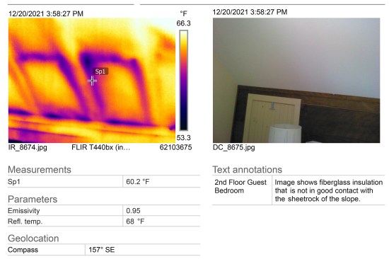

Typical of a Cape, the second-floor interiors have knee walls on…
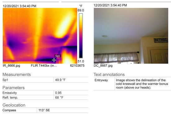
Walking the first-floor interior with the couple, I noticed it was warm; 75°F plus. When asked about their heating habits, they informed me that they liked it warm and didn’t use temperature set-backs at night or when the home was unoccupied. I suggested that the temperature differential between the above-average warm interior and the cold exterior may be exacerbating heat drive out of the home through unwanted ceiling leaks and recommended lowering the thermostat and using set-backs to help reduce the ice damming, though this would not eliminate the problem.
Dueling insulation methods. Typical of a Cape, the second-floor interiors had knee walls on either side; the walls sloped inward from the top of the knee walls following the 9:12-pitch roof lines to a narrow, flat ceiling.
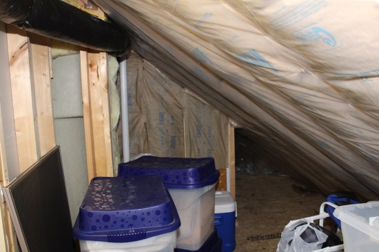
In the main house, the homeowners used the triangular-shaped space behind the knee walls for storage, which they accessed via well-sealed but uninsulated hatches. I crawled into the storage spaces and found that the original builder insulated on the slopes (the kraft-faced fiberglass batts were exposed to the interior). In the rafter bays, he ran insulation baffles and fiberglass insulation from the soffits to the small attic space above the narrow, flat ceiling. The Propavent baffles provided a channel for airflow from the soffit to the ridge vent.
Conversely, the garage wing was insulated on the ceiling flat and the bonus room’s knee walls. After squeezing into the space behind the bonus-room knee wall via the adjoining storage space under the inside corner of the L-shaped roof, I was surprised to find that the builder had used two different insulation methods for the home. Typically, builders choose one installation method or the other when insulating Cape-style homes in the area where I work. He may have decided it would be easier to insulate the garage wing’s 2-foot-on-center attic trusses on the flat and knee walls. (See illustration, “Two Methods of Insulating the Cape,” below).
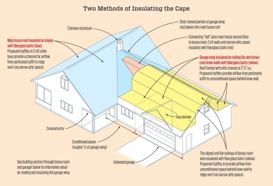
The main house was insulated on the slopes, while the garage wing was insulated on the ceiling flat and bonus-room knee walls. The bonus room runs the length of the garage wing’s second floor over both conditioned and unconditioned spaces.
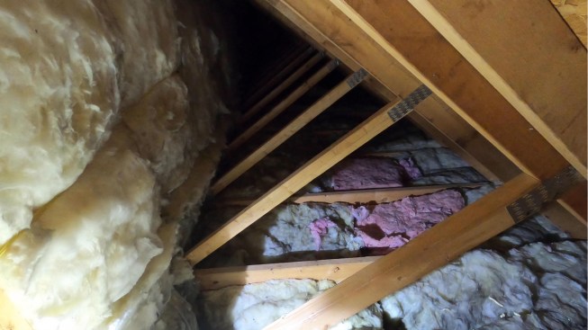
In the main house, the space behind the knee wall is used for storage. Here, kraft-faced fiberglass batts had been installed in the rafter bays. Propavent baffles between the batts and underside of roof sheathing were butted end to end and were not air-sealed (not shown). This, along with the baffles being loosely affixed to the underside of sheathing, allowed some wind washing of the insulation, reducing its performance.
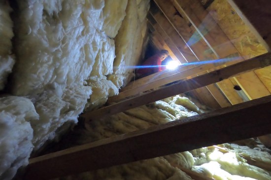
Here, in the unconditioned space behind the bonus-room knee walls, the bays of the vertical 2×4 web members of the attic trusses (which act as the knee wall) were infilled with 6-inch-thick kraft-faced R-21 batts, while the bays of the 2×10 bottom truss chords were infilled with 9-inch-thick kraft-faced R-30 batts. The fiberglass batt installations in the knee wall, ceiling, and connection “hall” area (not shown) were Grade II-level at best with large areas of Grade III work. (For information about insulation assembly grading, see Allison Bailes’ Energy Vanguard blog, “How to Grade the Installation Quality of Insulation” and JLC “Q&A: Installing Faced Batts.”)
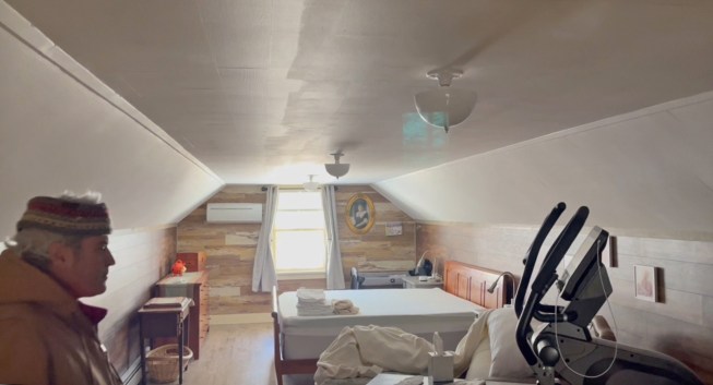
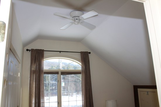
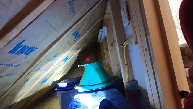
The 12×34 bonus room is used as an exercise room and guest bedroom. Without the benefit of side dormers to bring in light, the room’s length and 6’-8”-high ceiling give the room a somewhat cavernous feel (the dormer above the garage door is a faux dormer installed to divert water away from the door opening).
A Phased Solution for a Leaky House
We detected numerous air bypasses at wall and ceiling locations during the energy assessment, forming a clearer picture of where targeted improvements could be made. I sent the homeowners the results of the energy audit and my recommendations. They chose to just focus on work related to eliminating the sources of warm air escaping the house and heating the underside of the sheathing in the garage wing. The client’s budget and their desire to avoid, if possible, any interior demolition were factors in their decision.
Work on the main house, such as properly sealing the existing Propavent baffles to prevent wind washing of the insulation and covering the exposed kraft-faced batts (a potential fire hazard) with drywall would be done at a later date, in warmer weather. I also recommended installing 4 inches of XPS insulation on the bottom of the garage ceiling to act as a thermal break and increase air-sealing. This too was pushed to the “Phase II” portion of the energy retrofit work.
Phase I. Ideally, I would have preferred to move the thermal envelope to the slopes and triangular cheek walls in the garage area, but after analyzing the attic trusses, I determined the 2×8 top truss chords were too shallow to easily vent and insulate on the slope. Also, two-thirds of the garage wing space was located over a cold garage, so I reluctantly proposed keeping the insulation layer on the flat and the knee walls (see illustration, below).
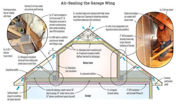
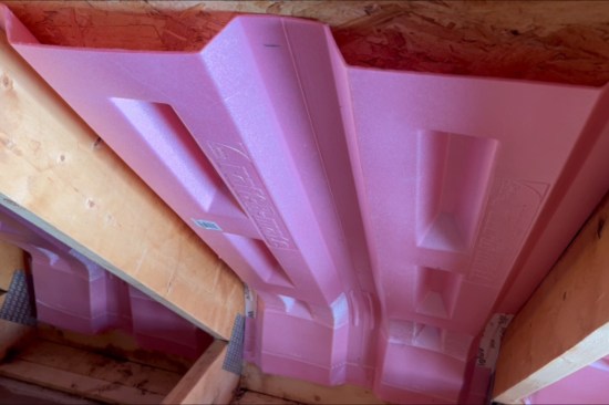
A layer of 2-inch gray DuPont XPS insulation serves as the primary air barrier between the bonus room and cold space behind the knee wall. The building section is taken through the bonus room and unheated garage portion of the garage wing.
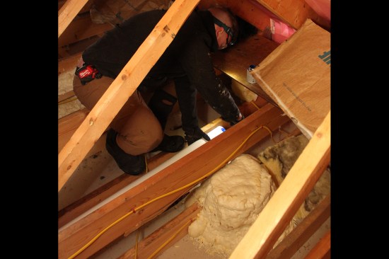
I assembled a work crew and we started out by making two holes in the gable-end wall of the garage wing to access the spaces behind the bonus-room knee walls. We removed fiberglass insulation from the ceiling and under the bonus-room floor. In the bays of the vertical 2×4 web members of the attic trusses (which acted as the knee wall), the previous builder had stapled 6-inch-thick, kraft-face R-21 batts. We removed 2 inches of fiberglass from the back of the batts to prevent compressing them when we installed a layer of 2-inch XPS insulation; the XPS would serve as the primary air barrier between the bonus room and the cold space behind the knee wall.
At the sloped and flat ceilings of the bonus room, we couldn’t readily improve the insulation and air-sealing from below (the ceiling was already quite low at 6 feet 8 inches high). So, we left the existing fiberglass insulation in place and checked the existing insulation baffles for blockages.
We carefully cut and dryfit rigid XPS pieces to make sure they were relatively tight around the attic trusses and the insulation baffles at the top of the knee wall, then screwed them in place through insulation washers and air-sealed all the seams and panel edges.
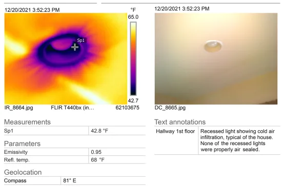
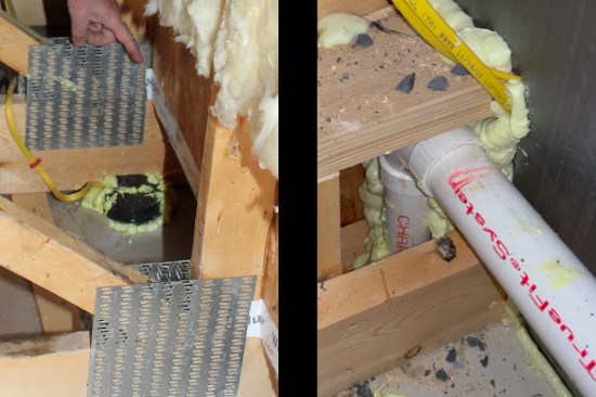
The usual suspects. Along the eaves, we air-sealed the top plates from above and installed new insulation baffles. We taped the fragile Propavents at their articulated bends to help prevent them from breaking. At recessed lighting and bath-fan locations, we foamed in either site-built OSB or manufactured covers. The two fan units vented out through long lengths of 4-inch flex duct, which we replaced with 4-inch rigid PVC sloped 1/4 inch per foot toward the soffit vents. Rounding off the usual air-sealing suspects, all the partition top plates and knee-wall outlets were foamed in.
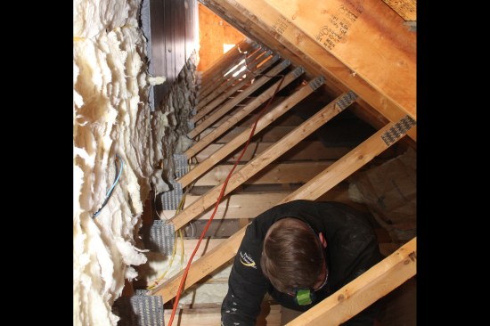
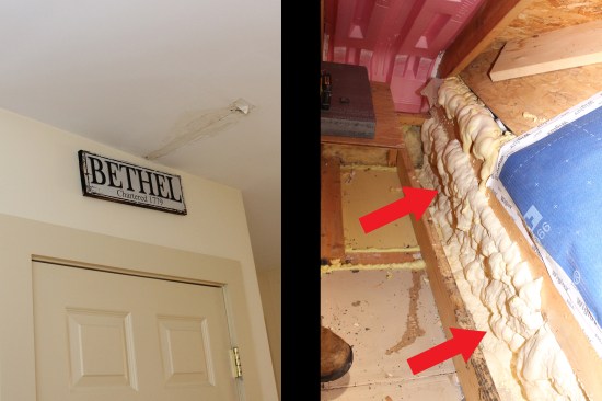
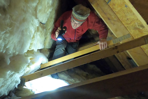
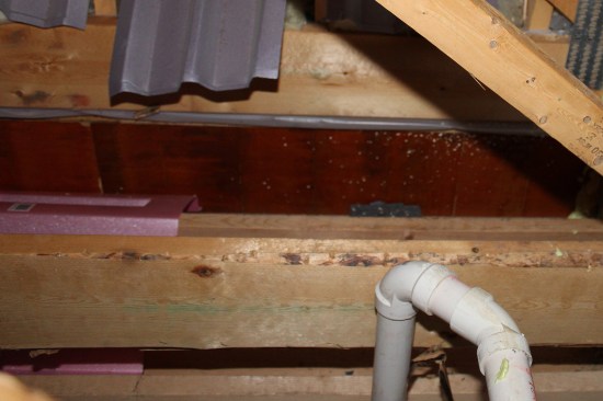
Holes were cut in the gable-end wall of the garage wing to acces…
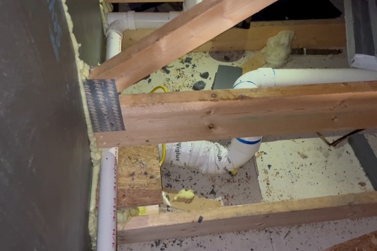
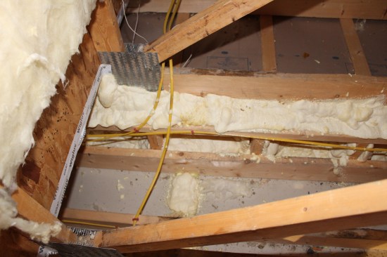
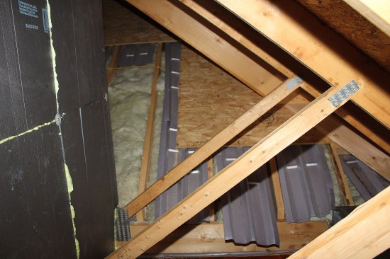
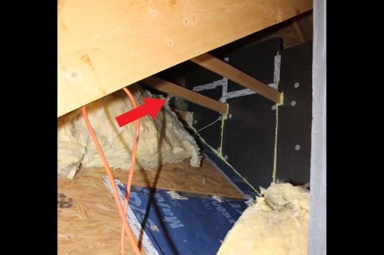
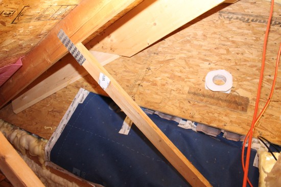
The not-so-usual suspects. Where the two insulation methods interfaced at the intersection of the garage wing and main house, the original builder seemed to have thrown in the towel with regards to completing the thermal envelope. He left the main roof under the stick-framed section forming the valleys partially sheathed with large areas of exposed fiberglass and Propavents loosely placed. To cover the exposed batts, we taped Majvest diffusion-open membrane with Wigluv high-performance tape on the back of the existing baffles, then taped the Majvest to the sheathing to create a continuous air-seal; we needed to make sure the existing baffles would keep venting to the main roof’s ridge vent.
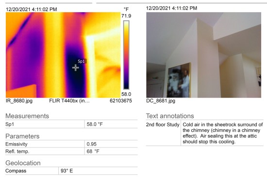
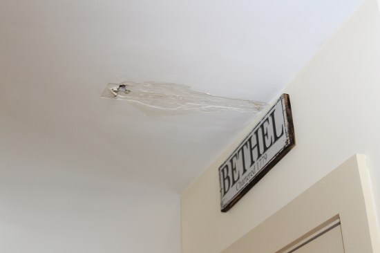
Another unusual find was an interior leak that was caused by condensation forming on the LVL beam supporting the cantilevered eaves of the main house. When conditions were right, condensation would form on the “cold” LVL where it entered the attic space (the beam was not air-sealed or covered with insulation), causing water to drip through the gaps between the framing and damage the drywall ceiling below. We air-sealed the end of the LVL with foam using a froth pack.
Photos by Chris West and Tim Healey; illustrations by Tim Healey