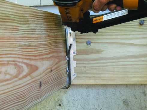
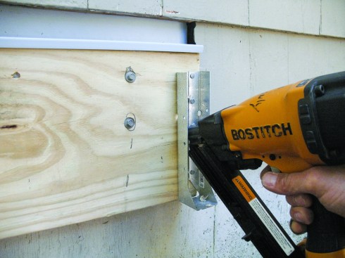

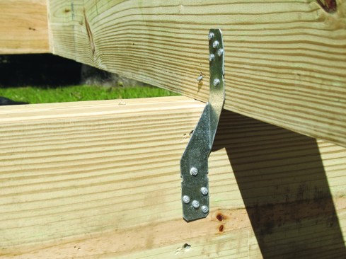

Figure 1. Install joist hangers tight to the wood. The Joist Cli…
Nails were the only things made of metal in the first decks I worked on over 30 years ago. Nails mounted the ledger to the house, joists to the ledger and beam, and guardrail posts to the rim — and made every other connection. Like most deck builders today, I still use nails, but now I use them to mount metal hardware that’s specifically designed to secure each connection. Even though I work in a coastal hurricane zone and use a fair number of metal connectors to frame a house, board for board I use more metal hardware to frame a deck than a house. Metal hardware makes sense; it makes for a stronger, safer deck.
Over the past half-dozen years, I’ve had to be more careful planning which deck hardware to use. Many connections have several hardware solutions to sort through, and new hardware has replaced less-than-ideal field solutions. Plus, selecting the right hardware is only part of the job — it has to be installed properly to work as intended.
Joist Hangers
Joist hangers are boring, right? Not so fast: These work horses may cause your laborer to cringe at the notion of filling hundreds of holes with tiny nails, but installing them properly requires considerable care, starting with fitting them to the joist and ledger or header. The seat needs to cradle the joist bottom evenly and the sides tightly. I like to tweak the sides inward just a little so when the hanger slips on from beneath the joist, the sides wrap in snug. This usually keeps the hanger seat flat across the bottom too. The Joist Clip (FastCap; 888/443-3748, fastcap.com) works great to clamp the hanger in place for hand or power nailing (Figure 1).
Also, in order for the hanger to support the joist adequately, the joist has to be fit to within 1⁄8 inch of the ledger, beam, or header you’re attaching it to. The 2-inch-deep hanger seat doesn’t mean you can be sloppy with your crosscuts.
The most common joist-hanger designs incorporate diagonal “shear” nailing, where the fasteners toenail through the joist into the ledger or header (Figure 2). These models specifically call for 10d common nails — that means 3-inch-long, 0.148-inch-diameter nails. Longer nails can be used, but shorter nails are not permitted. I’ve more than once had to have a laborer pull out the 11⁄2-inch or 21⁄2-inch nails he blasted in with a pneumatic nailer because “they were already loaded in the gun.”
Specialty Hangers Solve Awkward Connections
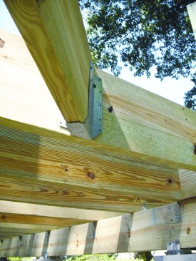
Skewed hangers mount joists laid out at 45 degrees to the supporting ledger or beams (Figure 3). They’ve been around for a long time, but it’s amazing how many deck frames I see where 45-degree beveled joist ends are just nailed to the supporting members.
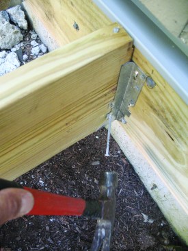
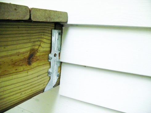
Concealed-flange hangers are only a few years old and haven’t yet become well-known (Figure 4). They are great for a couple of applications, the main one being to secure the end joists. I’d always been frustrated figuring out how to install hangers to pick up the end joists at the ledger. The outside flange just hangs out there in mid-air, begging to be beat around the end of the ledger, an unapproved field modification that I’ve been known to make (Figure 5).
Better choices than mashing over a hanger are extending the ledger to pick up the flange or doubling the last joist, with the inner of the two receiving a single hanger. But concealed-flange hangers solve the problem elegantly. The nailing flanges on concealed-flange hangers are turned into the joist pocket, so they can be installed right up to the end of the ledger or rim beam. Once the joist is set, all you see is the strip of steel cradling the joist.
Concealed-flange hangers are also useful where the joist layout causes a conventional hanger flange to fall on a ledger-fastener head (Figure 6). Rather than countersinking the fastener (a practice that severely reduces holding power), you can use a concealed-flange hanger to avoid the problem all together. And along the same line, concealed-flange hangers enable you to install the tension rods or bolts alongside joists when installing lateral-load or guardrail-post reinforcement brackets, where conventional hanger flanges get in the way of running the through-bolts.
Keep two things in mind when using concealed-flange hangers: They must be mounted to the ledger or beam before the joist is placed, and the joist must be trimmed about 3⁄16 inch shorter to account for the thickness of the in-turned flanges and fastener heads.
Post Bases
Most 6×6 and 4×4 treated lumber is rated for “ground contact,” but you’re asking for trouble burying the ends in a concrete footing. It’s only a matter of time before the elements and organisms start breaking down the posts molecule by molecule. I prefer metal post bases that raise the wood off the concrete 1 inch or more and out of harm’s way (Figure 7). Most post bases provide both lateral and uplift load resistance through the legs that nail, screw, or bolt to the bottom sides of the post.
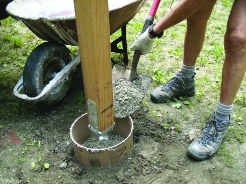
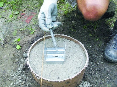
The type of post-base I choose depends on the deck configuration. Elevated decks allow for the option of temporarily supporting the deck frame and installing footings and posts later. I like to use cast-in-place post bases on these decks (Figure 8). First I dig the footing holes, cut the posts, and fasten a base to each post; then I hang the post from the beam over the footing; and last I pour the concrete.
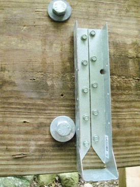
For deck frames that are close to grade, the footings have to be installed first. When the grade is flat, the post bases and anchor bolts are easy to align to a string. But lining them up can be tricky when the grade and footing tops are uneven. Rather than risk a misplaced post base, I generally opt to use a model that can be anchored with a wedge anchor bolt or an epoxy anchor bolt (Figure 9). Once the footings are cured, I can pinpoint the post-base locations, drill a hole, and install the anchor and base.
Post-to-Beam Connectors
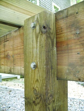
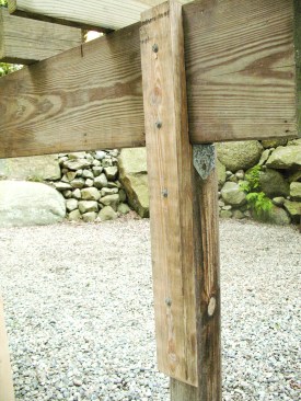
Hardware choices for post-to-beam connections probably outnumber those for any other deck framing connection. My preferred post-to-beam connection, though, doesn’t rely on hardware at all. I like to notch 6×6 posts with beam seats, leaving a 21⁄4-inch leg that extends up to the top of the beam, then through-bolt the beam to the legs (Figure 10). The legs not only provide lateral and uplift load resistance, they also secure the beam from rotating — something common hardware doesn’t do. When working with 4×4 posts, I bolt or screw a length of 2-by that spans from the top of the beam down the back of the 4×4 about 2 feet (Figure 11).
The cost of a beam-to-post connector versus a couple of bolts or structural screws is pretty close, but if you’re figuring labor, it’s probably faster to meet the minimum lateral and uplift load requirement using connector hardware. But unlike the previous two methods, it puts a shiny piece of hardware in plain view.
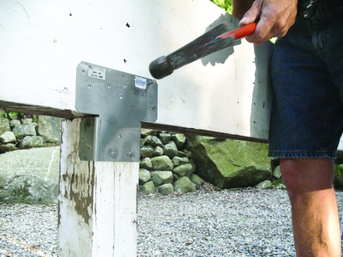
I often do install post caps on deck upgrades. Retrofit post caps are designed for beams that sit on top of posts and for beams that are bolted to either side of posts (Figure 12). The caps for beams resting on posts slide onto the side of the post and beam. The key to installing these properly is to use them in pairs to achieve the rated load capacities.
Beams bolted alongside posts are usually mounted in pairs — one on each side of the post. The beams need to be resting directly on a support, however, to handle the deck load. Side-mounting hardware solves the problem. The connectors can be mounted with nails or through-bolts for additional load capacity.
Joist to Beam
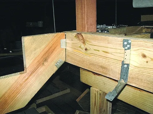
While toenails may provide the required uplift and lateral resistance, many inspectors are looking for a more reliable connection, like hurricane ties (Figure 13), to connect joists to the beam. They are inexpensive and ward off any questions. I toenail each joist to the layout line and return later to mount the hurricane clips. By alternating them on either side of the beam from joist to joist, there’s less chance of driving the beam out of alignment with the posts below. On an elevated deck where I’m going to be installing the footings and post bases after building the frame, the hardware pieces hang the beam and posts during the process.
Stair Stringer to Deck Frame
This is a tricky connection with a lot of inadequate field solutions. Back-screwing or back-nailing blocking to the rim joist to hang a set of stair stringers may be adequate for a two-riser set of stairs, but stairs with numerous risers need a more solid connection. For several years I used connectors made for mounting rafters to the side of a ridge beam.
In 2009, specially designed stringer-mounting hardware became available (Figure 14). This stringer hardware requires that the head of the stringers be cut plumb and contact the deck frame. That means the top of the last tread flushes out with the top of the deck framing, and the first tread will be an extension of the decking. This is a change for deck builders used to installing the head of stringers one riser height lower than the deck level. The hardware pieces can be mounted to the rim joist with structural screws to address the code provision prohibiting stairs from being mounted with nails subject to withdrawal, which any straight-in nail or toenail is prone to.
One consequence of having the top tread flush with the decking is that the last post of the deck’s guardrail will be too low to catch the guardrail coming up the stair. There are two solutions. You can add an extra post at the front edge of the top riser, and run the guardrail for the top tread level. Alternatively, you can inset the top of the stair into a jog in the frame.
will lose.
Do use the right nail. Common, sinker, cooler, box, 16d, 10d, 8d — these terms relate in part to the nail-shank diameter and length, but the terms are sometimes used incorrectly. When the wrong nail is installed in a hole, there’s a penalty: Either the hardware won’t perform at the rated load or you have to pull the nail out and replace it.
Do look at the manufacturer’s nail requirements. The most accurate way to know what size nails to use is to check the actual diameter and length requirements for each piece of hardware. Some hardware pieces require different size nails in different holes. Take joist hangers, for instance. The flanges typically require 11⁄2-inch-long, 0.148-inch-diameter nails, but the diagonal nails that penetrate the joist and into the ledger or header need to be a minimum of 3 inches long by a 0.148-inch diameter. Many brands of nails, loose and collated, are now specifically made for metal hardware and include ID marks on the heads. The marks make it easier for building inspectors to know the nail size without having to pull any out. Marked nails don’t cost that much more and they eliminate any questions.
Don’t make field modifications. As soon as you deform a piece of metal, it’s toast. Years ago, I beat hangers to the right shape to mount 45-degree joists or wrap around the end of a ledger board. Now manufacturers produce connectors for just about every detail you’ll commonly encounter.
Do watch the air pressure and depth-of-drive settings on metal-connector nailers. Overdriven nails deform the metal and damage the integrity of the connector. I like to set my nailers to leave nails a little proud, and then I set the heads flush with a light hammer blow.
Do use connectors as they are intended to be used. Though a piece of hardware may seem like it will tie a connection together, unless it’s been tested for the purpose, it can’t be trusted. Just because the makers stamp it out doesn’t mean you can invent new uses.
“,”_id”:”00000157-4e43-d8ff-ab5f-7f67b0be0000″,”_type”:”00000147-834b-d6e5-a1df-ffff91990002″,”alignment”:”left”}” data-id=”00000147-834b-d6e5-a1df-ffffa64b0000″ class=”enhancement”>Article Sidebar PlaceholderRail-Post Connectors
Whether I’m installing site-built wood guardrails or synthetic railing systems, I secure the posts to the frame of the deck using metal brackets designed for the purpose rather than just bolting them to the rim joist. Most manufactured railing systems rely on structural wood posts. Since those railing systems must comply with the structural requirements of ASTM D-7032, and the responsibility for securing the posts to the frame is left up to the deck builder, there’s a lot riding on the way I make the connection. Nearly every set of railing instructions requires or recommends that the post-to-deck connection be designed by an engineer. Short of going that route, I look to hardware that has supporting testing and an ICC-ES report.
Most deck builders have skated by the guardrail load requirements that have been in the building codes for a long time, because building officials have continued to permit traditional bolting and blocking methods. But as the research presented in PDB (Question & Answer, May/June 2007; free at deckmagazine.com) gets into the hands of building officials and they learn about the issue through continuing education programs sponsored by hardware manufacturers, more inspectors will be looking for either an engineered guardrail-post-to-frame connection or a hardware solution.
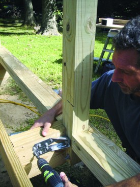
In 2009, hardware makers introduced specially designed connectors that are faster to install and less costly than previous models and seismic hardware used for the purpose (Figure 15). The new hardware requires only a single bolt through the post and mounts to the joist with structural screws rather than additional bolts. The screws zip in fast with impact drivers and don’t require the extra step of pilot holes.
Ledger Connection
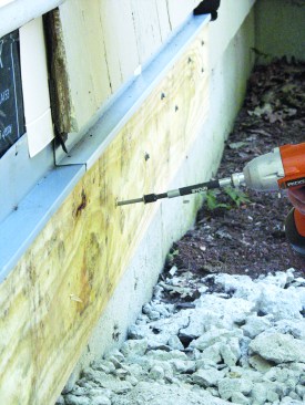
When I first saw engineered structural screws like those offered by FastenMaster (800/518-3569, fastenmaster.com), Simpson Strong-Tie (800/999-5099, strongtie.com), GRK Fasteners (800/263-0463, grkfasteners.com), and others, I couldn’t imagine the small-shanked screws had similar design capacities to those of 1⁄2-inch lag screws (Figure 16). After checking the shear values and doing a few deck load calculations to see how many of the structural screws I’d need for different size decks, I felt confident they were strong enough. And after using them once, I haven’t gone back to commodity lag screws. The time savings are phenomenal and they’re cost competitive; what’s not to like?
One new issue that we’ll be dealing with for the next few years as more jurisdictions adopt the 2009 IRC will be lateral-load connections for decks. Though for many years the IRC has required that decks attached to buildings be designed to handle the lateral load in addition to the vertical load, a new drawing (Figure 502.2.2.3) and Section (R502.2.2.3) in the code will likely be construed as a requirement rather than a permitted prescriptive solution (Figure 17). In that connection, two pairs of hold-down connectors are bolted to joists on the deck and within the house. They’re connected to each other with long 1⁄2-inch bolts.
I think many building officials who don’t read the IRC commentary or other explanations of the new section will interpret the drawing as a requirement and start looking for lateral-load hold-down hardware on every deck. That became obvious to me during a code-change seminar given by a state building official, who said that decks are now required to be constructed following the figure in the IRC. And even building officials who understand that the design in the figure is just one way to address lateral loads will be looking for lateral loads to be addressed somehow when we build decks going forward, because they are alerted to the issue.
800/999-5099
strongtie.com
USP Structural Connectors
800/328-5934
uspconnectors.com“,”_id”:”00000157-4e44-d1fd-abdf-defcb25e0000″,”_type”:”00000147-834b-d6e5-a1df-ffff91990002″,”alignment”:”left”}” data-id=”00000147-834b-d6e5-a1df-ffffa64b0000″ class=”enhancement”>Article Sidebar PlaceholderI’ve installed the bracketed joist-to-joist connection on a few decks. A couple of things to keep in mind: The deck joist and house joist don’t have to be aligned perfectly — the tension rod can be angled to account for the offset. The rod can also slope down on a deck that is stepped lower than the floor of the house it is connected to. And even though the IRC 2009 drawing doesn’t show it, there are blocking designs for when the house joists run perpendicular to the deck joists.