Confronted with the task of installing a sink or vanity cabinet, you may be tempted to speedily hack out a window in the cabinet’s back to accommodate roughed-in plumbing protruding from the drywall, then slide it home. But I’m of a mind that the interior appearance of a cabinet matters almost as much as the exterior, therefore I take the time to accurately align cabinet cut-outs with the roughed-in piping.
The following is a simple method I use to accomplish a precise alignment.
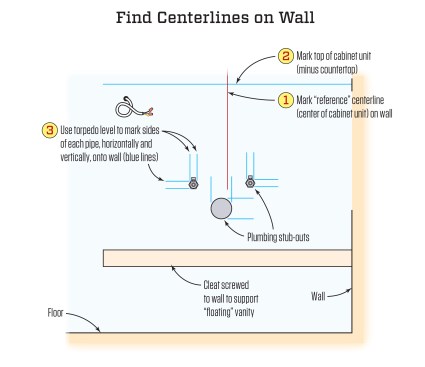
Establishing a centerline. I start by determining the cabinet’s centerline and marking it on the back of the case. Then I mark the cabinet’s centerline on the wall in its final location. These two vertical center-lines serve as reference lines from which I’ll measure to guarantee precise left–right positioning.
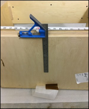
He starts by marking a centerline on the cabinet’s back panel with a combo square, then he marks the centerline on the wall at its ultimate location.
Next, I make a level line on the wall at the exact final height of the cabinet (minus the countertop thickness); I’ll measure from this line to mark the wall with the horizontal centerlines of each protrusion.
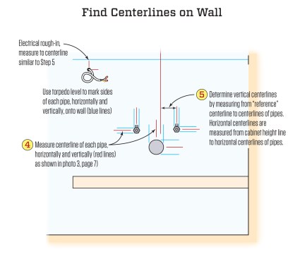
With the cabinet’s centerline and top horizontal laid out, I use a torpedo level to outline the sides of each protrusion, both vertically and horizontally, onto the wall. What I’m after is the centerline of each pipe, which I find by measuring between my lines. After marking the center, I use a torpedo level to draw a centerline.

After marking the outer dimensions of the drainpipe on the wall with a torpedo level, the author finds the center (at the 5-inch mark) by lining up the same increment on either side of the 4- and 6-inch marks on a tape (left). Then he uses a torpedo level to draw the pipe’s vertical centerline (right).
Now it’s a fairly simple matter of measuring between the cabinet centerline and the individual centerlines of the pipes.
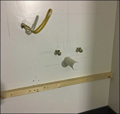
The existing conditions are precisely plotted on the wall.
Layout marks include the cabinet’s centerline, the top of the vanity…
…and plumbing and electrical centerlines.
For this, I move away from the hook on my tape and work from the 1-inch mark, commonly referred to as “burning the inch of the tape.” Some say this invites error, but I believe this increases accuracy when measuring. Either way, stay focused because every dimension you take from the wall has to be transferred to the back of the cabinet in the opposite direction; left-of-center on the wall becomes right-of-center on the cabinet back.
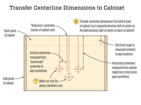
Layout information from the wall is transferred to vanity’s back panel, but in the opposite direction. Vertical centerlines of pipes are located by measuring from the reference, or benchmark, centerline. Horizontal centerlines are located by measuring from the cabinet height line.
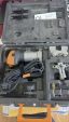
Cut-outs. When drilling through the back, I choose a sharp spade bit as close to the pipe diameter as is reasonable; for example, a 3/4-inch bit for a 1/2-inch supply-line pipe. For larger openings, such as for a 2-inch drainpipe, I use a hole saw.
When drilling from the back of the cabinet, I stop short of punching through, letting just the tip of the pilot bit go through the back. Using the pilot bit hole as a guide, I complete the holes from inside the cabinet, thus avoiding tear-out around the opening.
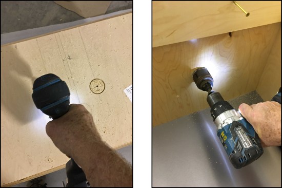
A hole saw, going partway through the back panel, is used to make the cut-outs (left). Working from the inside, the hole saw punches through the finish face (right).
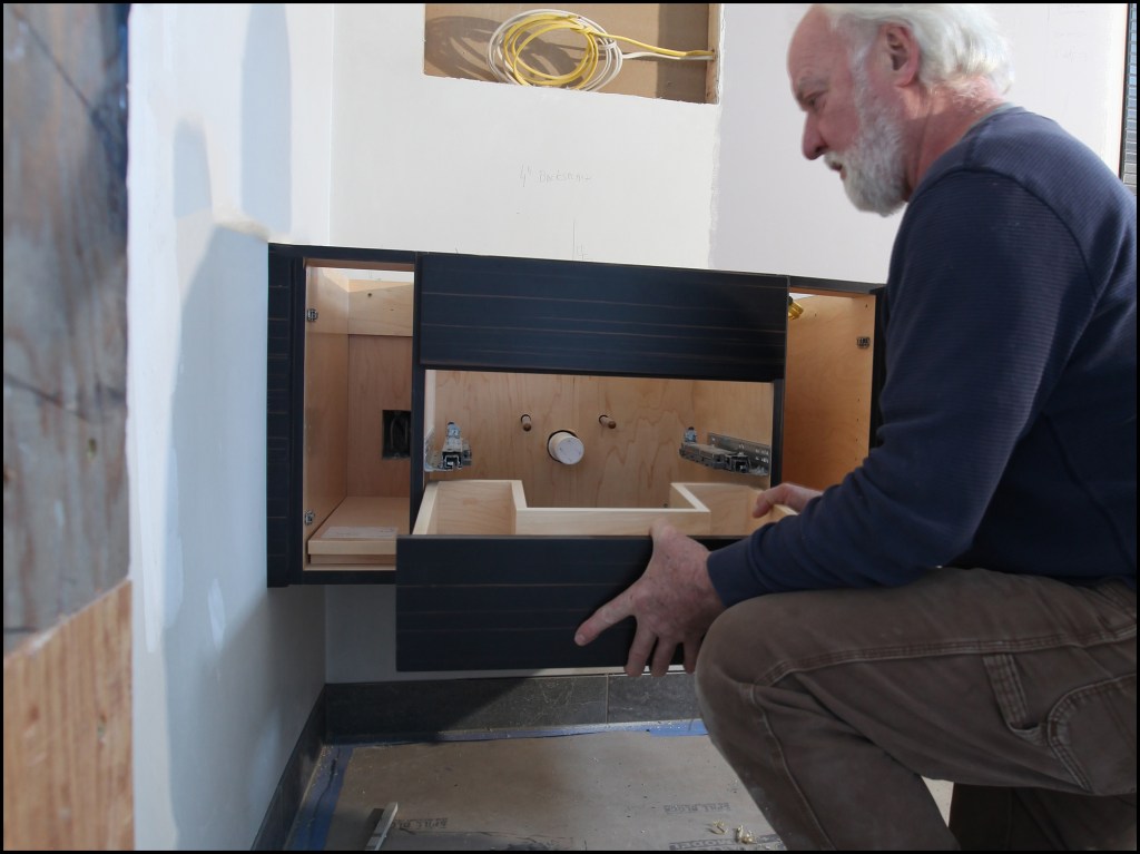
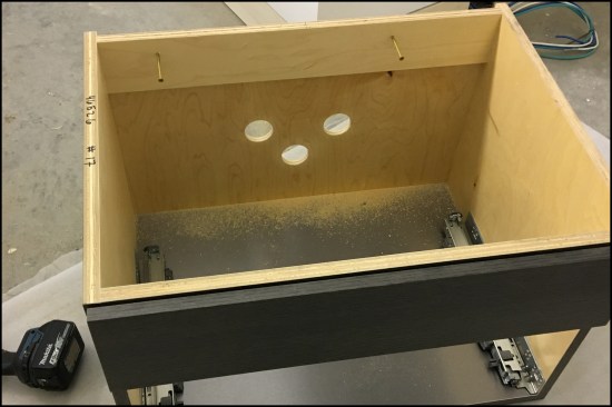
With cut-outs completed, the vanity cabinet is easily slid into place. Electrical boxes inside the cabinet are measured and cut similarly.
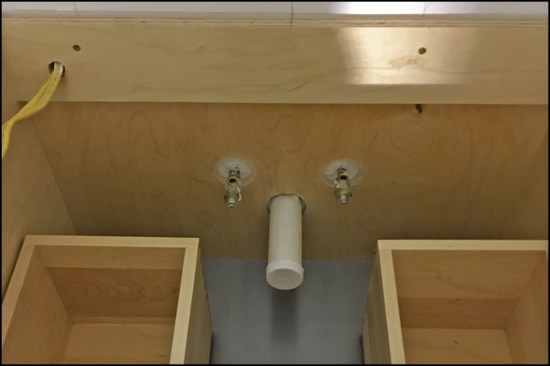
Here, the holes for the supply lines were cut larger to accommodate shut-off valves installed on the stub-outs; valves are typically installed after the cabinet installation.
The example vanity cabinet installed. A 1/2-inch hole was made to run power to an outlet on the side of the vanity (upper left corner of photo).
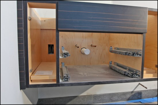
More typical, “tighter” 3/4-inch holes were cut for 1/2-inch supply-line pipes in another vanity unit. Also, an electrical box was cut inside the cabinet (electrical boxes are similarly measured, though cut-outs are made with a multi-tool or jigsaw).
Photos by Dave Holbrook; illustrations by Tim Healey